Image processing method, image recording method, image processing device and image file format

a technology of image processing and recording method, applied in the field of image processing technique, can solve the problems of difficult to record video data with a high resolution every frame, equipment will consume excessive power and generate excessive heat, and it is difficult to read out all pixels at a video data frame rate of about 30 fps

Active Publication Date: 2007-09-27
PANASONIC CORP
View PDF9 Cites 69 Cited by
  • Summary
  • Abstract
  • Description
  • Claims
  • Application Information

AI Technical Summary

Benefits of technology

[0017] According to the present invention, a high-resolution image is obtained only for the window region being a portion of the entire image, whereby the pixel read-out process does not require a long period of time. Therefore, it is possible to record the low-resolution video data without dropping frames. Since the high-resolution image is obtained for each frame, the high-resolution image is not shifted in time with respect to the low-resolution image, thus allowing for the process to appropriately learn the resolution conversion rule. Since the position of the window region changes every frame, the resolution conversion rule is learned based on data from a large area of the image, but not data from a limited area of the image. Thus, the process can appropriately learn the resolution conversion rule. Moreover, the high-resolution image does not need to be stored, and only the low-resolution video data and the resolution conversion rule need to be stored, whereby it is possible to considerably reduce the amount of information to be stored as compared with conventional techniques. In the resolution increasing process, the resolution conversion rule, which is learned for the window region being a portion of the entire image, is used for the entire image of the recorded low-resolution video data. Unless the image characteristics of the object in the window region are significantly different from those outside the window region, it is possible to realize a high-precision resolution conversion across the entire image.
[0018] In the present invention, the process may produce the low-resolution image in the window region through an image filtering process such as sub sampling or averaging on the high-resolution image. Then, it is not necessary to read out the low-resolution image for the window region, and it is therefore possible to further reduce the total number of pixels that need to be read out.
[0019] In the present invention, the window region may be moved every frame so that the entire image is scanned by the window region over a plurality of frames. Then, the process learns the resolution conversion rule for the entire image over a plurality of frames, thus realizing the resolution increasing process with an even higher precision.
[0021] The present invention is not limited to resolution increasing processes, but is applicable to resolution conversions in general. The present invention can also be effectively used in producing a low-resolution image to be displayed on a low-resolution display system such as a mobile telephone, for example.

Problems solved by technology

Where video data of an HD (High Definition) TV or better quality is desired, it is very difficult to read out all pixels at a video data frame rate of about 30 fps due to the large number of pixels even if the image pick-up device has enough pixels.
If such a high-speed read-out process is performed forcibly, the equipment will consume excessive power and generate excessive heat.
Therefore, with state-of-the-art techniques, it is difficult to record video data with a high resolution every frame, and it is possible only to obtain a high-resolution image per a few frames of video data.
However, the conventional techniques have the following problems.
The problem is that the searching process imposes a heavy load, and it may result in incorrect pixel associations.
If the object deforms or turns simultaneously with its movement, the process may not find points to be associated with each other, whereby the process fails.
However, if the conversion factor is increased to about four, the total area of a high-resolution image to be read out is 16 times as great as that of a low-resolution image, and the process of reading out high-resolution images will take excessive amounts of time.
As a result, there will be a significant increase in the number of frames to be dropped from the recorded video data, and the quality is likely to deteriorate due to the frame dropping in the video data.
Thus, high-quality images may not be derived appropriately if the image characteristics at the fixed position are different from those of other positions.
This presents a significant problem especially when increasing the resolution of video data, whereby it is likely that a sufficient precision will not be obtained in the resolution conversion.

Method used


Image

  • Image processing method, image recording method, image processing device and image file format
  • Image processing method, image recording method, image processing device and image file format
  • Image processing method, image recording method, image processing device and image file format

Examples


first embodiment

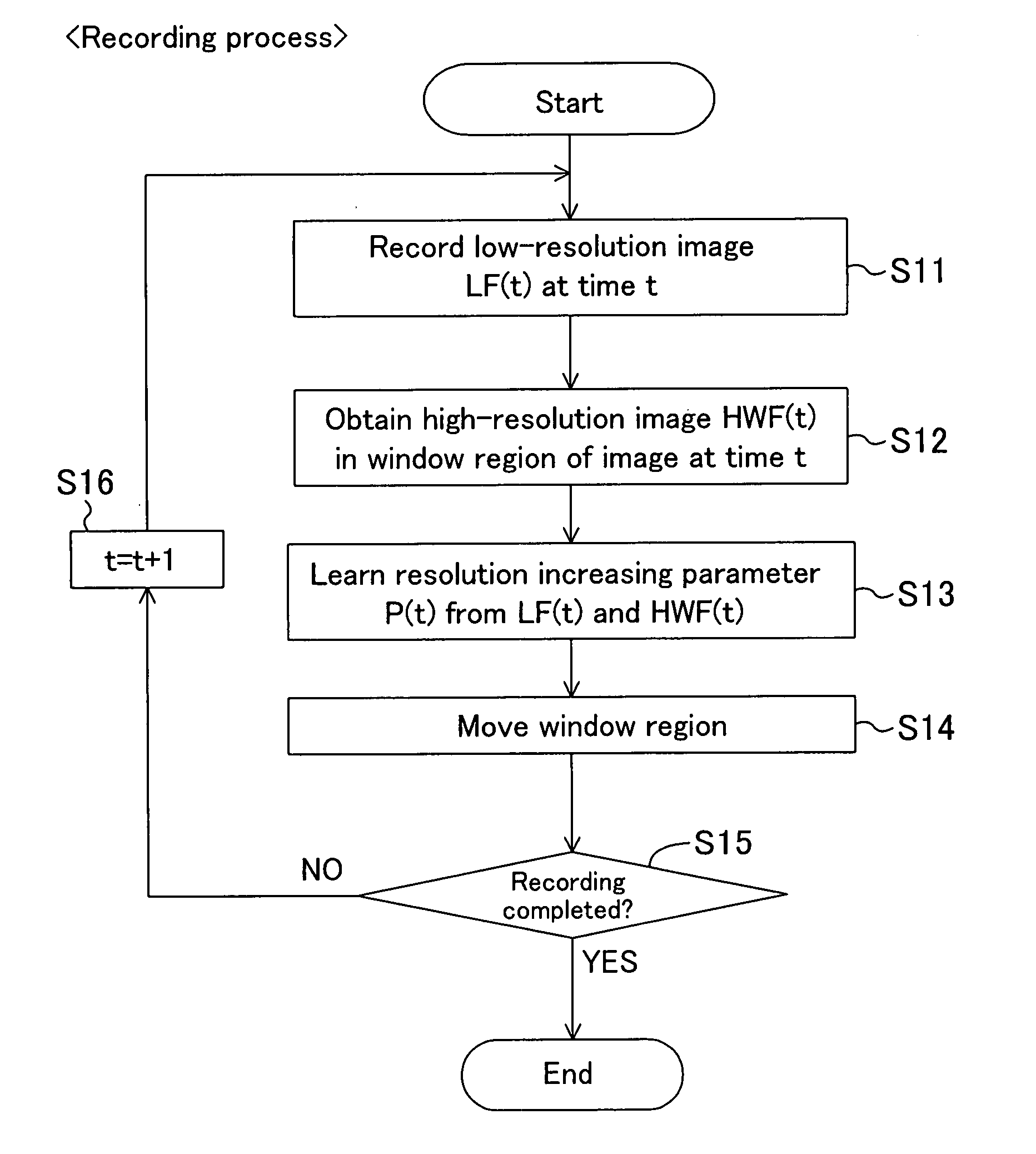
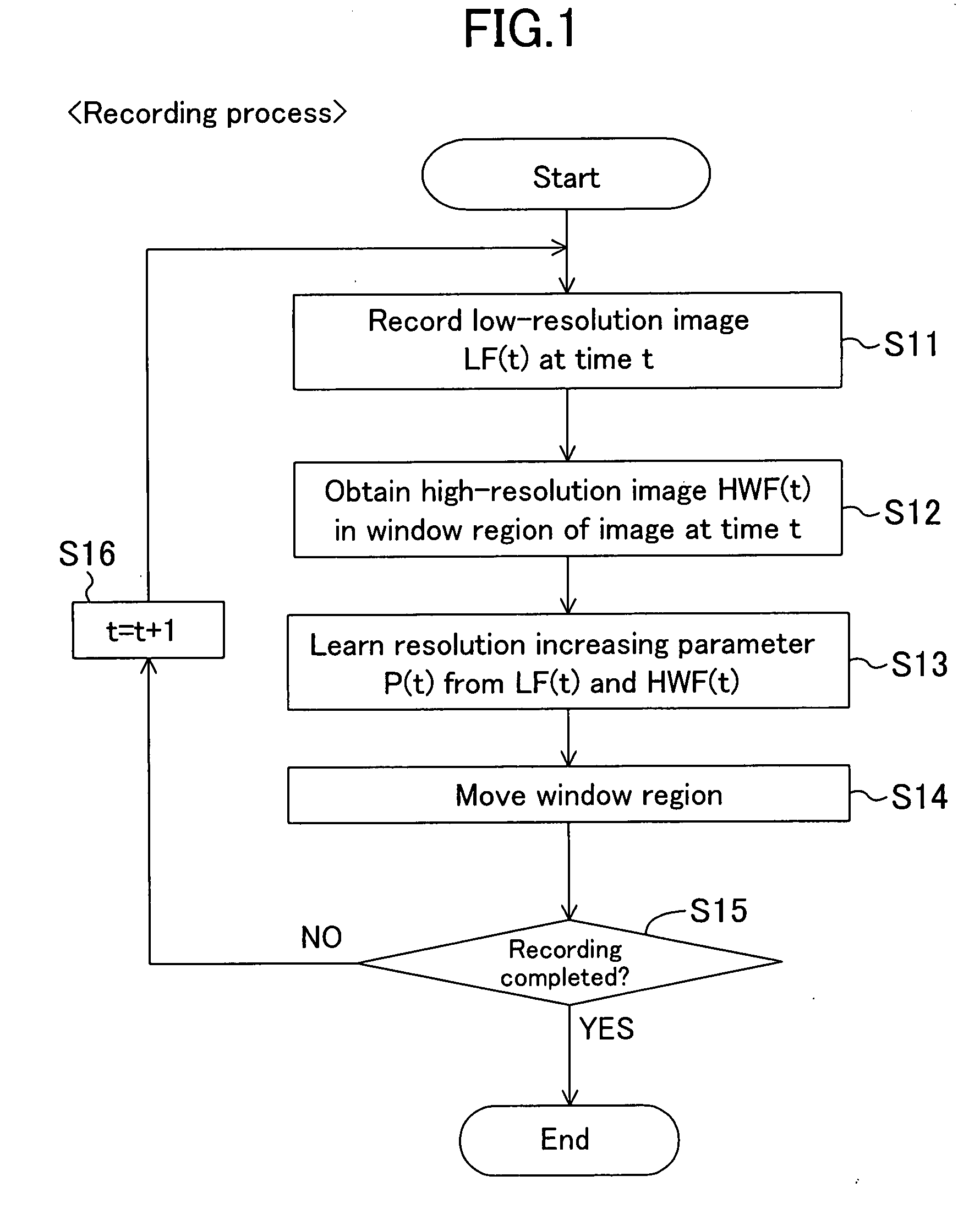
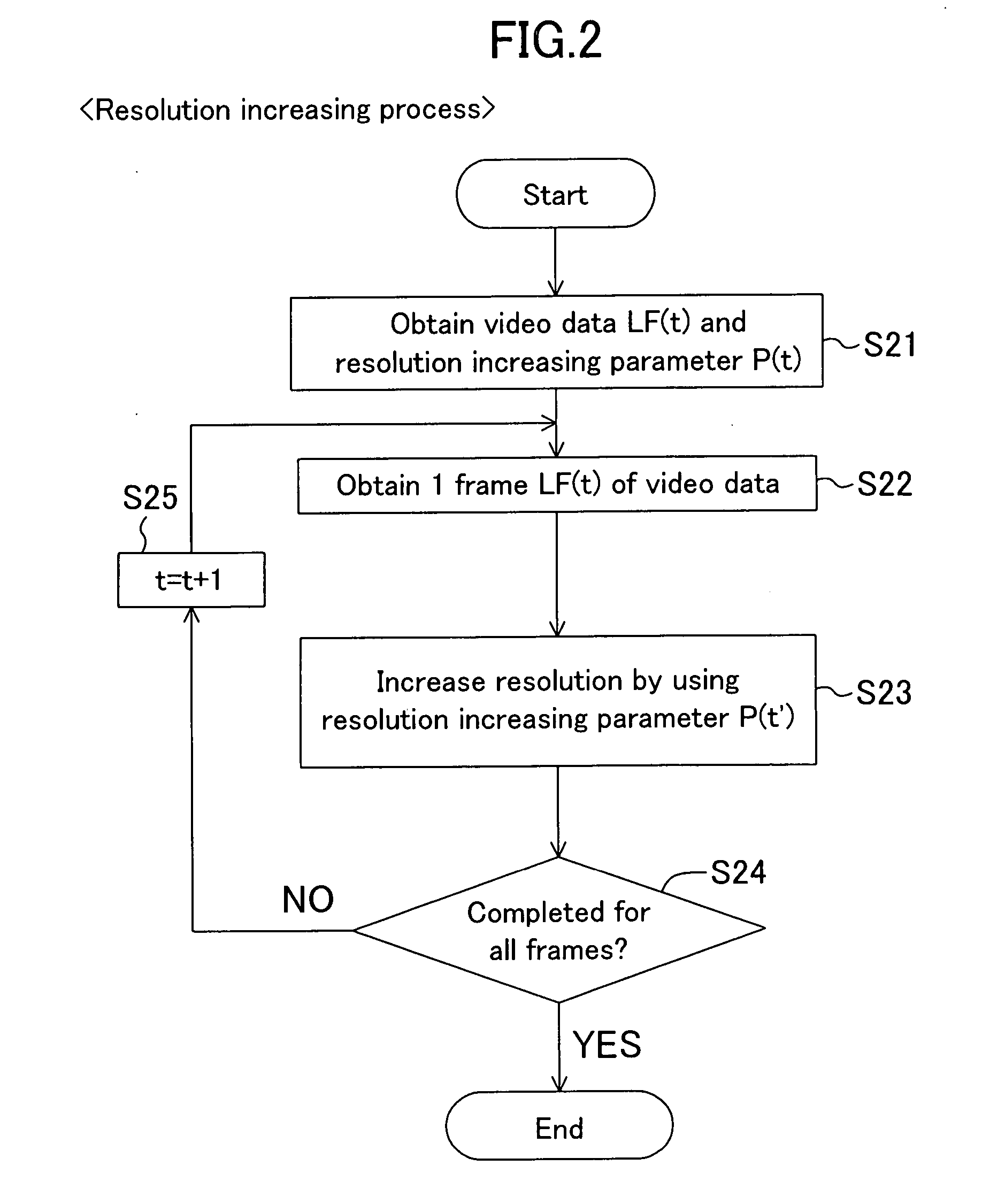
[0084]FIGS. 1 and 2 are flow charts showing an image processing method according to a first embodiment of the present invention. FIG. 1 shows a recording process of recording a scene, and FIG. 2 shows a resolution increasing process of reproducing and displaying the recorded video data. The process of FIG. 1 and that of FIG. 2 correspond to the video recording process and the reproduction process of watching the recorded video on a display, respectively.

[0085] The recording process of FIG. 1 first obtains and stores a low-resolution image LF(t) at time t(S11). At the same time, the process obtains a high-resolution image HWF(t) in a window region being a portion of the image frame (S12). Since the high-resolution image HWF(t) is only used in a later process, it does not need to be stored as video data. Based on these images LF(t) and HWF(t) of different resolutions, the process learns and stores a resolution increasing parameter P(t) as a resolution conversion rule (S13). Then, the...

second embodiment

[0112] A second embodiment of the present invention is based on the first embodiment as described above, and is directed to a specific device configuration. In this embodiment, the recording process is performed by using a camcorder including a multi-pixel-resolution image pick-up section capable of recording multi-pixel-resolution video data as described above. The multi-pixel-resolution image pick-up section is realized by using an XY address type imaging device such as a CMOS-type image pick-up sensor.

[0113]FIG. 8 is a block diagram showing an exemplary configuration of an image processing device of the present embodiment, wherein the present invention is applied to a camcorder. An image processing device 10 of FIG. 8 includes a lens 101, a multi-pixel-resolution image pick-up section 102, a low-resolution frame memory 103 for storing one frame LF(t) of low-resolution video data, a low-resolution video recording section 104 for recording low-resolution video data DLF, a high-res...

third embodiment

[0168]FIG. 23 is a block diagram showing an exemplary configuration of an image processing device according to a third embodiment of the present invention, wherein the present invention is applied to a camcorder as in FIG. 8. The configuration differs from that of FIG. 8 in that the low-resolution frame memory 103 is omitted, and a multi-pixel-resolution video recording section 401 for recording multi-pixel-resolution compressed video data DMC is provided instead of the low-resolution video recording section 104 for recording the low-resolution video data DLF. Thus, while video data with a lowered resolution is recorded in the second embodiment, image data obtained by the multi-pixel-resolution image pick-up section 102 is stored as it is in the present embodiment. By effectively using the obtained multi-pixel-resolution video data without lowering its resolution, the present embodiment aims to improve the performance of the resolution increasing process.

[0169] When the record butt...


PUM


Abstract

A recording process records low-resolution video data while obtaining a high-resolution image in a window region being a portion of an entire image. Then, the process learns, as a resolution conversion rule, a resolution increasing parameter by using the high-resolution image. In a resolution increasing process, the resolution of the recorded low-resolution video data is increased by using the resolution increasing parameter learned in the recording process.

Description

CROSS-REFERENCE TO RELATED APPLICATIONS [0001] This is a continuation of Application PCT / JP2006 / 315655, filed on Aug. 8, 2006. This Non-provisional application claims priority under 35 U.S.C. §119(a) on Patent Application No. 2005-262610 filed in Japan on Sep. 9, 2005, the entire contents of which are hereby incorporated by reference.BACKGROUND OF THE INVENTION [0002] 1. Field of the Invention [0003] The present invention relates to an image processing technique, and more particularly to a technique for resolution conversion such as increasing the resolution of video data. [0004] 2. Description of the Background Art [0005] With the spread of digital image devices such as digital video cameras and digital still cameras, it has become common that high-resolution digital images are handled by various types of input / output devices. Particularly, with still images, the image pick-up device of an ordinary consumer digital still camera has five megapixels or more, and some products include...

Claims


Application Information

Patent Timeline
Patent Type & Authority Applications(United States)
IPC IPC(8): H04N7/26G06T3/00G06T3/40G06T5/50H04N5/225H04N5/232H04N5/765H04N5/91H04N5/92
CPCG06T3/4053H04N5/232H04N5/341H04N5/3454H04N5/772H04N5/91H04N19/59H04N9/7921H04N19/63H04N19/42H04N19/20H04N19/423H04N9/045H04N25/40H04N25/443
Inventor KANAMORI, KATSUHIROKOMOBUCHI, HIROYOSHIMOTOMURA, HIDETOKONDO, KENJIAZUMA, TAKEO
Owner PANASONIC CORP
Why Eureka
Try Eureka