Auto-focus performance

a technology of autofocus and performance, applied in the direction of camera focusing arrangement, printers, instruments, etc., can solve the problems of more difficult peripheral areas to achieve the same optical performance, the disadvantages of the known “focus and recompose” technique become apparent, and the average speed is not as fast, so as to achieve the effect of easy rotation angl

Inactive Publication Date: 2007-09-27
NOKIA CORP
View PDF4 Cites 5 Cited by
  • Summary
  • Abstract
  • Description
  • Claims
  • Application Information

AI Technical Summary

Benefits of technology

[0009] In view of the above mentioned problem, it is, inter alia an object of the present invention to improve the focus performance of an optical device like a camera, a method for using this camera and a program algorithm to be implemented in such a camera.
[0010] Furthermore, the invention is intended to solve or reduce the focus error problems that are associated with the known focus-and-recompose-technique.
[0013] The solution according to the invention is easy to implement and very cost-effective to realize. The present invention may be implemented in any type of advanced camera systems, e.g. cameras, which are able to produce a shallow depth of field. This type of photography is preferred in the field of portrait photography: when keeping the target subject focused while keeping the background blurred at the same time, the target subject is separated from the background in a nice looking manner. The invention can also be implemented in optical devices capable of macro photography where shallow depths of field can be achieved also with small camera sensors and optics. Thus, the very fast and effective focusing technique which the “focus and recompose method” takes advantage from, can be maintained for arbitrary applications by using only one central focus sensor. It is also in some cases possible to make the center AF sensor even more sensitive and more accurate, since the cost of the other AF sensors is reduced or removed.
[0018] This type of sensor can e.g. be an accelerometer which keeps track of the camera movement during reorientation after the focus lock in the first camera position thus obtaining easily the rotation angle α.

Problems solved by technology

Moreover, the center location for AF sensor is also preferred for usability reasons, and because it is more difficult for the peripheral areas to achieve the same optical performance as the center.
The technical disadvantages of this known “focus and recompose” technique become apparent when the target subject goes out of the depth of field of the camera, e.g. in those applications which are directed to shallow depth of field situations, like portrait photography.
However, the disadvantage of utilizing several focus detectors is that this procedure is typically not as fast and that it is not as easy to select the different focusing points compared to the use of a single central focus point.
Another disadvantage is that in many cameras the focus points outside the central focus point are not as accurate and sensitive, which leads to the result that in low-light conditions the focus cannot be locked by another than the central focus point.
Thus, a larger focusing error results from using a less accurate auto-focus sensor.

Method used


Image

  • Auto-focus performance
  • Auto-focus performance
  • Auto-focus performance

Examples


Embodiment Construction

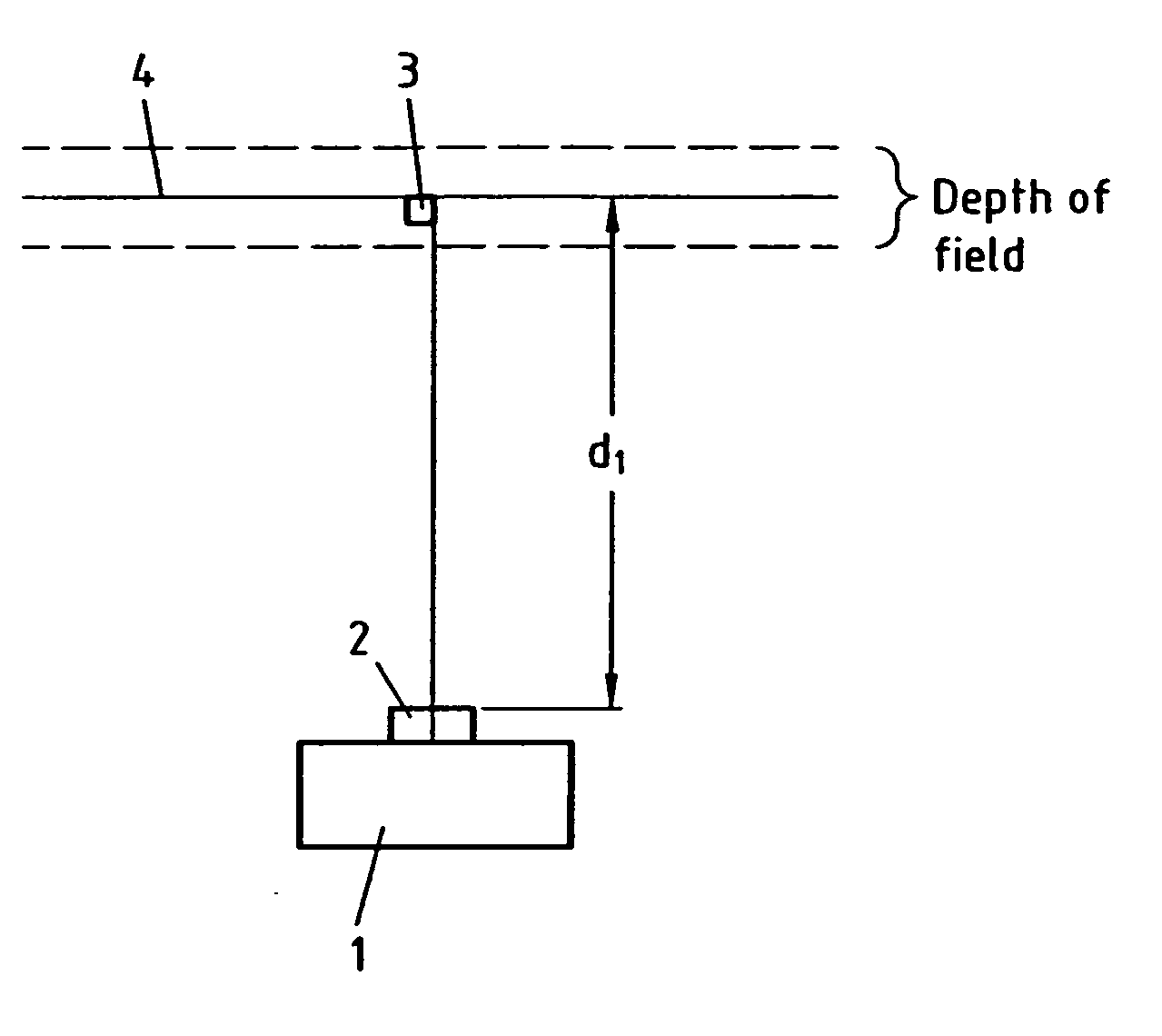
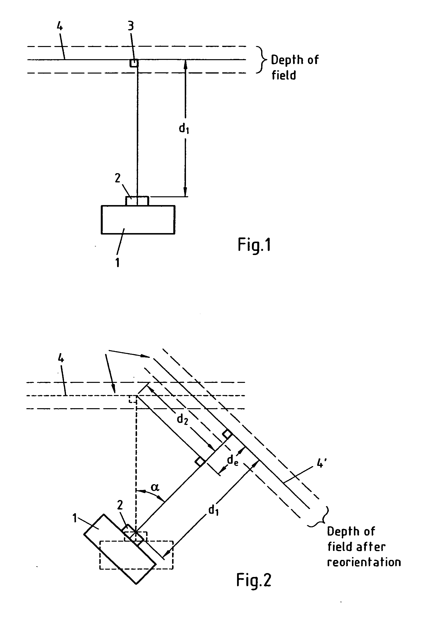
[0033] The optical imaging device according to the preferred embodiment of the present invention comprises a camera housing 1 and at least one lens unit 2 to be mounted to the camera housing 1. Moreover, an optical storage unit (not shown) is comprised in the camera, which can be an optical film in traditional (“non-digital”) cameras or a processor receiving digital signals from a CMOS image sensor to be used in a digital camera. A generalized image device may for instance include an image sensing arrangement comprising the lens assembly 2 and an image sensor. The imaging sensing arrangement captures an image and converts the captured image into an electrical form. Or, it can be captured on film. If done electrically, the electrical signal produced by the apparatus is led to an analog to digital converter which converts the analog signal into a digital form. From the converter the digitized signal is taken into a signal processor where it is processed to create an image file. The ou...


PUM


Abstract

A device, method and a computer program product are shown for correcting the focus error in an optical device, wherein in a first position of the optical device at least one focus detector is focused onto a given image plane of the target subject and the distance (d1) between the optical device and the given image plane is locked and wherein in a second position of the optical device following a reorientation of the optical device for achieving the desired framing of the image the shutter is released, the method comprising sensing a distance vector parallel to the focus plane after reorientation between the first position and the second position after reorientation, calculating a focus correction value (de) from the sensed distance vector and adding the focus correction value (de) as a corrective to the locked focus distance (d1).

Description

FIELD OF THE INVENTION [0001] The present invention relates to a method, a device and an algorithm directed to an improved auto-focus performance in an optical device, like a camera. BACKGROUND OF THE INVENTION [0002] Optical imaging devices, like Single-Lens-Reflex (SLR) cameras, which are widely used in the field of photography, are usually equipped with an auto-focus system, by which the camera lens system automatically focuses the image on a selected part of the target subject. The detector for accomplishing the auto-focus (AF) function is usually located at the center of the frame because this position is generally more sensitive and more accurate than the other parts of the frame. Moreover, the center location for AF sensor is also preferred for usability reasons, and because it is more difficult for the peripheral areas to achieve the same optical performance as the center. [0003] Under those circumstances, in which the part of the subject which should be focused, is not in c...

Claims


Application Information

Patent Timeline
Patent Type & Authority Applications(United States)
IPC IPC(8): G03B13/34
CPCG02B7/287H04N5/23212G03B13/34G02B7/36H04N23/67
Inventor NIKKANEN, JARNO
Owner NOKIA CORP
Why Eureka
Try Eureka