
Method and apparatus for drying coated film, and method for manufacturing optical film

a coating film and optical film technology, applied in the direction of drying machines with progressive movements, lighting and heating apparatus, furniture, etc., can solve the problems of uneven drying between the central part of the web and the end of the web, insufficient to achieve uniform drying, and unregulated air flow there, so as to achieve excellent surface and uneven drying

Inactive Publication Date: 2007-10-04
FUJIFILM CORP
View PDF11 Cites 20 Cited by
  • Summary
  • Abstract
  • Description
  • Claims
  • Application Information

AI Technical Summary

Benefits of technology

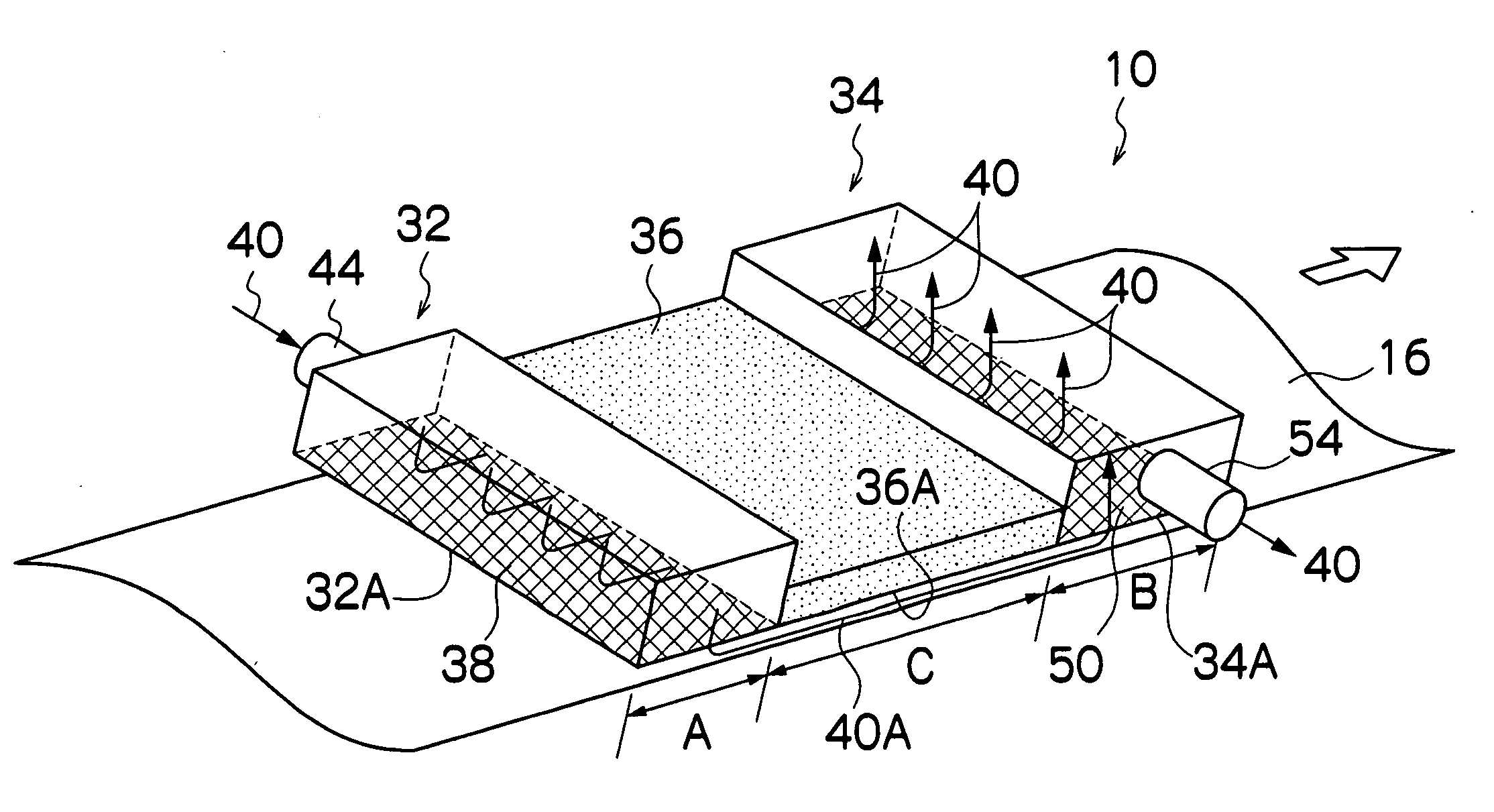
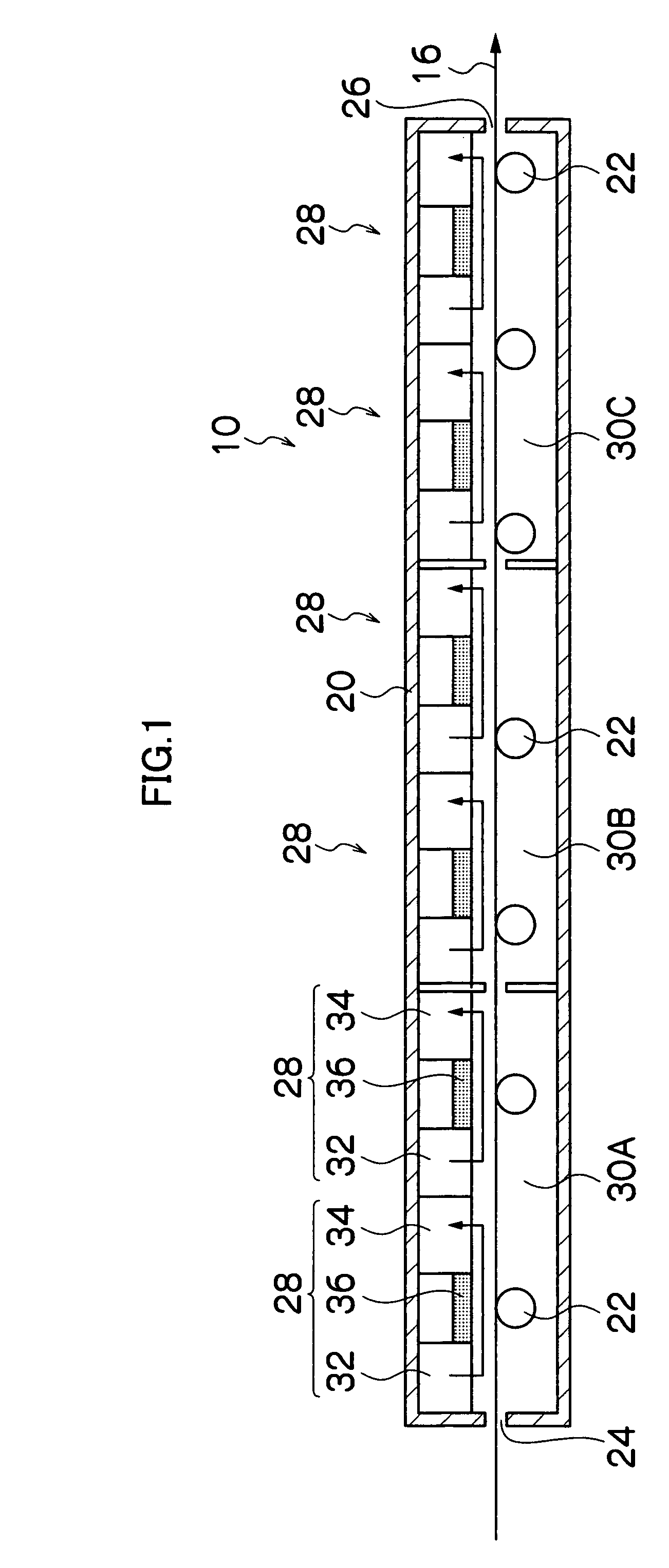
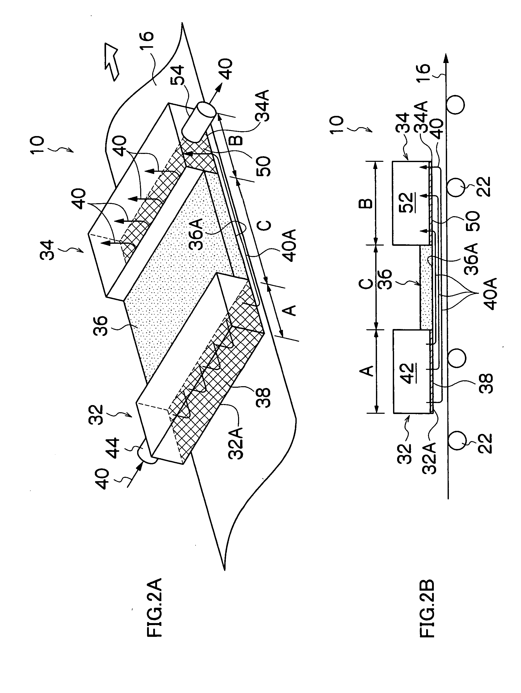
The present invention provides a method and apparatus for drying a coated film by using a tunnel-shaped dry case with a porous distributor to achieve a uniform drying of the film without causing unevenness on the surface. The method involves blowing dry air towards the surface of the film through an outlet port and sucking it through an inlet port, creating a stream of dry air that flows parallel to the running direction of the web. The invention also provides a porous distributor at both the outlet and inlet ports to ensure a gentle and smooth blow and suck of the dry air. The technical effect of the invention is to achieve a uniform drying of the film without causing unevenness on the surface.

Problems solved by technology

However, conventionally, as disclosed in the above Japanese Patent Application Laid-Open No. 9-73081, when a coating is performed at a room temperature, the air flow there has not been particularly regulated.
Alternatively, as disclosed in the above Japanese Patent Application Laid-Open Nos. 2000-157923 and 2003-126108, only a wind velocity has been regulated without providing such a case to prevent disturbance, both of which were insufficient to achieve an uniform drying just after a coating.
When the radial streams of dry air are considered from viewpoint of a drying of a coated film in a width direction of a web, more volume of the air flows along the both ends of the web than along the central part of the web, and this causes drying unevenness between the central part of the web and the ends of the web.
Particularly, a higher wind speed of the blown air increases the volume of the air along the both ends of the web, and this tends to cause drying unevenness.
The collision of the dry air masses causes an unrectified flow of dry air on the coated film surface, which in turn causes drying unevenness.

Method used


Image

  • Method and apparatus for drying coated film, and method for manufacturing optical film
  • Method and apparatus for drying coated film, and method for manufacturing optical film
  • Method and apparatus for drying coated film, and method for manufacturing optical film

Examples


example a

[0186]In Example A, drying unevenness obtained by using a drying apparatus according to the present invention was compared with that obtained by using a conventional drying apparatus.

[0187]An anti-glare and anti-reflection sheet was made by using manufacturing line shown in FIG. 7. As a coating device, a bar coater was used instead of the extrusion-type coating apparatus 76. The bar coater had a wire bar which had a diameter of 10 mm, and a wire which had a size of 75μ and was wound around the shaft.

(Preparation of Coating Solution for Anti-Glare Layer)

[0188]A coating solution for an anti-glare layer was prepared by dissolving a mixture of dipentaerithritol pentaacrylate and dipentaerithritol hexaacrylate (DPHA, Nippon Kayaku Co., Ltd.) 75 g and a coating solution for a hard coat containing a dispersion of zirconia ultrafine particles having a particle diameter of about 30 nm (DeSolite Z-7401, manufactured by JSR Co.) 240 g into a solvent mixture of methyl ethyl ketone / cyclohexanone...

example b

[0204]In Example B, the preferable aspects of examples of the present invention were examined, and a planar member (flat plate) 36 was interposed between the blowing device 32 and the suction device 34 so that the influence of the planar members 36 having different lengths in the running direction of the web onto the drying unevenness of a coated film surface was checked. The length of a drying zone was not particularly limited to 2 m.

[0205]In Test 1 to 6, the blowing device 32 including the outlet port 32A which had a length of 30 cm in the running direction of the web and was provided with a wire mesh of 250 mesh count as the first porous distributor 38, and the suction device 34 including the inlet port 34A which had a length of 20 cm in the running direction of the web and was provided with a wire mesh of 250 mesh count as the second porous distributor 50 were combined as a unit, and four of the units were arranged along a drying zone, and in Test 7, six of the units were arrang...

example c

[0215]In Example C, the preferable aspects of examples of the present invention were examined, and a distance D between the blowing device 32, the suction device 34, and the flat plate 36 and a coated film surface was changed so that the influence of the different distance D onto the drying unevenness of a coated film surface was checked.

[0216]In Test 8 to 11, the blowing device 32 including the outlet port 32A which had a length of 30 cm in the running direction of the web and was provided with a wire mesh of 250 mesh count as the first porous distributor 38, the suction device 34 including the inlet port 34A which had a length of 20 cm in the running direction of the web and was provided with a wire mesh of 250 mesh count as the second porous distributor 50, and the flat plate 36 having a length of 50 cm were combined as a unit, and four of the units were arranged along a drying zone. The coating speed was commonly set to be 20 m / min.

[0217]In Test 8, the distance D was set to be 5...


PUM


Abstract

A coated film drying method for drying a film which is coated on a surface of a web while the web is running through a tunnel-shaped dry case having a web entrance and a web exit, comprising the steps of:blowing dry air toward a surface of the coated film through an outlet port which is provided with a porous distributor; andsucking the dry air through an inlet port which is disposed at a position downstream or upstream of the position where the dry air is blown out and on the same side as that on which the outlet port is disposed relative to the coated film, so that a stream of the dry air which flows in a direction parallel to the running direction of the web is formed across the entire width of the surface of the coated film.

Description

BACKGROUND OF THE INVENTION[0001]1. Field of the Invention[0002]The present invention relates to method and apparatus for drying a coated film and a method for manufacturing an optical film, in particular, relates to a method and apparatus for drying a coated film and a method for manufacturing an optical film which can be preferably applied to a manufacturing of an optical film such as an optical compensation film, an anti-reflection film, and anti-glare film, and an optical film which is useful in improving unevenness of a liquid crystal layer.[0003]2. Description of the Related Art[0004]Recently, the demand for optical films has been increased. The optical films have various functions, and include, for example, an optical compensation film which is used as a phase difference board in a liquid crystal cell, an anti-reflection film, and an anti-glare film.[0005]Representative examples of the method for manufacturing such an optical film includes the one for forming a coating film w...

Claims


Application Information

Patent Timeline
Patent Type & Authority Applications(United States)
IPC IPC(8): F26B3/00
CPCF26B21/004F26B13/10
Inventor OGAWA, TOMONARINOJO, KAZUHIKOKOMINAMI, HIDEAKI
Owner FUJIFILM CORP
Learn More