Organic light emitting device
a light-emitting device and organic technology, applied in the direction of discharge tube/lamp details, luminescnet screen, discharge tube/lamp details, etc., can solve the problem of reducing light extraction efficiency, and achieve the effect of increasing light extraction efficiency and improving drive durability
- Summary
- Abstract
- Description
- Claims
- Application Information
AI Technical Summary
Benefits of technology
Problems solved by technology
Method used
Image
Examples
example 1
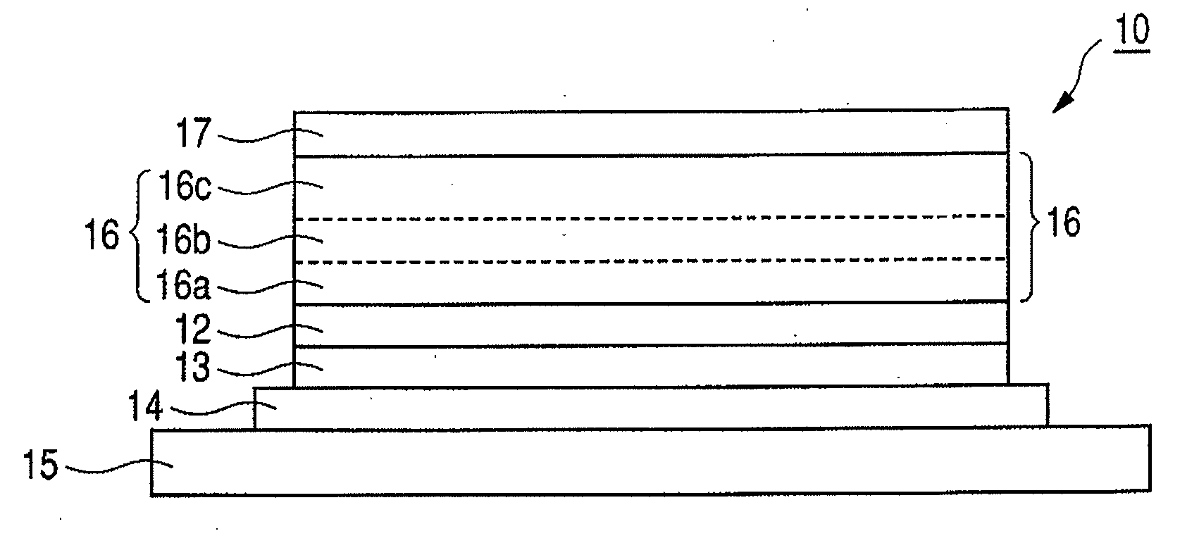
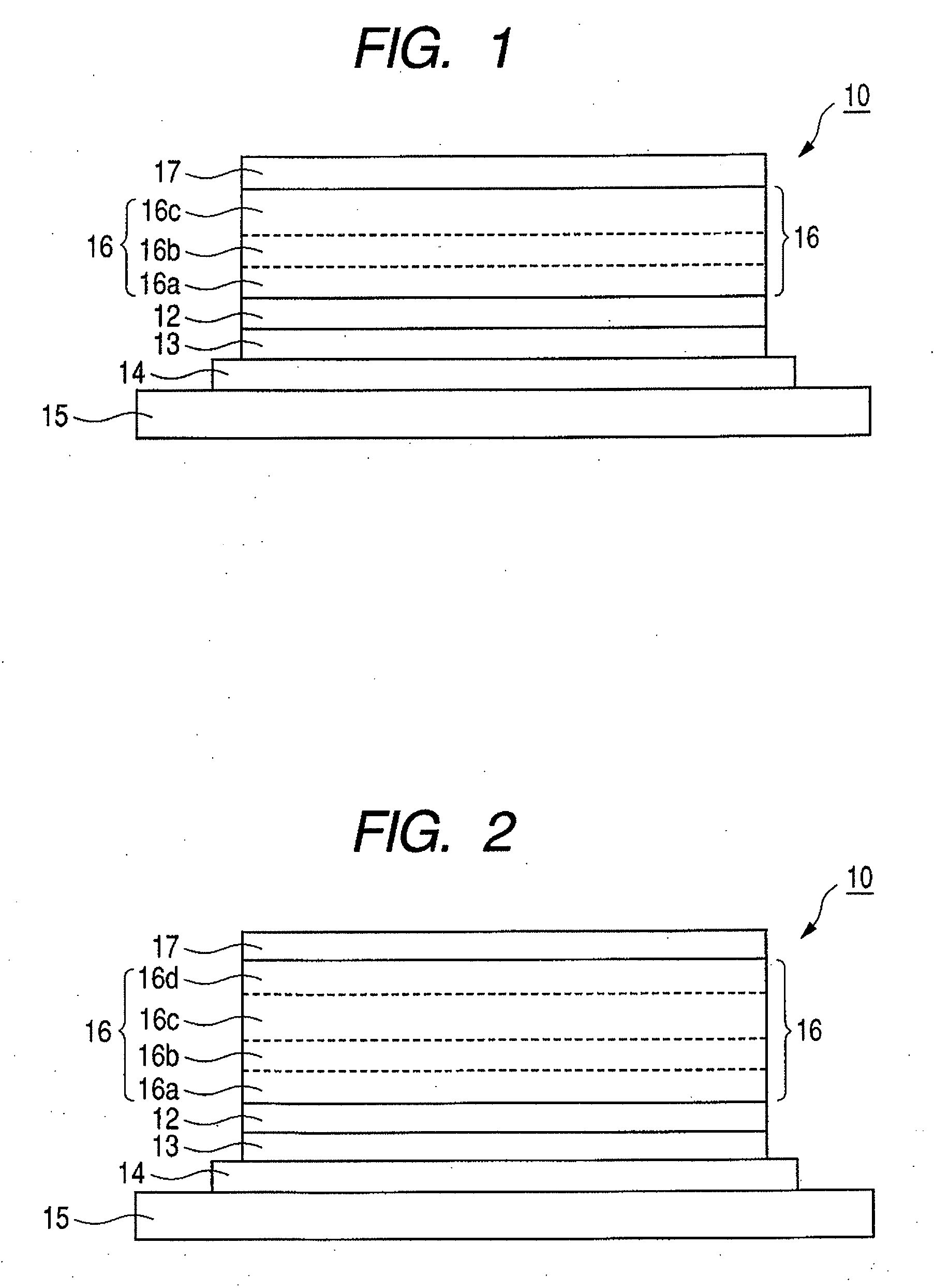
[0059]As shown in Table 1, the concentration of cesium carbonate in the electron injecting and transporting layer was set to 0.01% in the region a, 5.10% in the region b, 0.5% in the region c, and 4.9% in the region d to fabricate the organic light emitting device of Example 1. The region a, the region b, the region c, and the region d correspond to the regions 16a, 16b, 16c, and 16d in FIG. 1, respectively (the same shall apply in the following examples and comparative examples).
[0060]When the organic light emitting device of Example 1 was driven at a current density of 20 mA / cm2, it had a luminance of 463 cd / m2 and a drive voltage of 3.1 V. When the organic light emitting device of Example 1 was continuously driven at 20 mA / cm2, the time elapsed before the luminance was reduced to 90% was about 127 hr. When a current of 20 mA / cm2 was applied after a similar organic light emitting device to that of Example 1 which was fabricated under the same conditions was kept at normal temperat...
example 2
[0065]The concentration of cesium carbonate in the electron injecting and transporting layer was set to 0.01% in the region a, 4.8% in the region b, 0.5% in the region c, and 0.5% in the region d to fabricate the organic light emitting device of Example 2.
[0066]When the organic light emitting device of Example 2 was driven at a current density of 20 mA / cm2, it had a luminance of 470 cd / m2 and a drive voltage of 3.5 V. When the organic light emitting device of Example 2 was continuously driven at 20 mA / cm2, the time elapsed before the luminance was reduced to 90% was about 119 hr. That is, though the drive voltage rose in Example 2 as compared with Comparative Example 1, the luminance improved and the durability was almost at the same level as that of Comparative Example 1. When a current of 20 mA / cm2 was applied after a similar organic light emitting device to that of Example 2 which was fabricated under the same conditions was kept at normal temperature for about 200 days, the ligh...
example 3
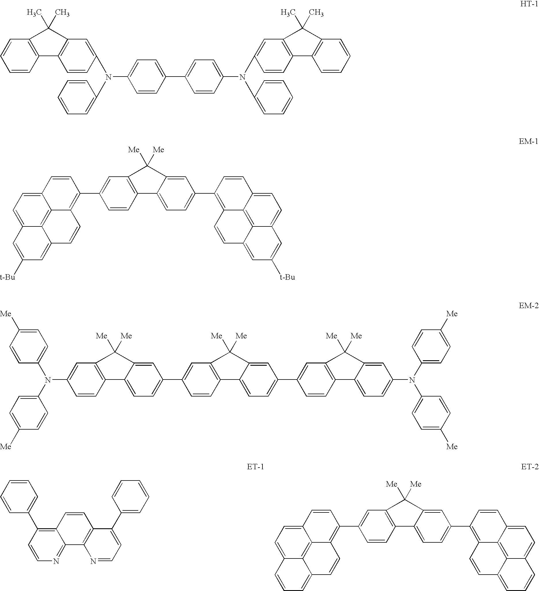
[0071]The organic light emitting device of Example 3 was fabricated in the same manner as in Example 1 except that a co-deposited layer from the vapor of ET-2 and cesium carbonate was used as the electron injecting and transporting layer.
[0072]When the organic light emitting device of Example 3 was driven at a current density of 20 mA / cm2, it had a luminance of 431 cd / m2 and a drive voltage of 3.2 V. When the device of Example 3 was continuously driven at 20 mA / cm2, the time elapsed before the luminance was reduced to 90% was about 121 hr. In Example 3, the drive voltage and the drive deterioration characteristics were almost at the same level as those of Example 1 and Example 2. When a current of 20 mA / cm2 was applied after a similar organic light emitting device to that of Example 3 which was fabricated under the same conditions was kept at normal temperature for about 200 days, the light emitting device had a drive voltage of 3.2 V.
[0073]As described above, according to the prese...
PUM
| Property | Measurement | Unit |
|---|---|---|
| thickness | aaaaa | aaaaa |
| thickness | aaaaa | aaaaa |
| thicknesses | aaaaa | aaaaa |
Abstract
Description
Claims
Application Information
 - R&D
- Intellectual Property
- Life Sciences
- Materials
- Tech Scout
- Unparalleled Data Quality
- Higher Quality Content
- 60% Fewer Hallucinations
Browse by: Latest US Patents, China's latest patents, Technical Efficacy Thesaurus, Application Domain, Technology Topic, Popular Technical Reports.
© 2025 PatSnap. All rights reserved.Legal|Privacy policy|Modern Slavery Act Transparency Statement|Sitemap|About US| Contact US: help@patsnap.com


