Method and apparatus for spatially modulated electric field generation and electro-optical tuning using liquid crystals

a technology of electric field generation and electrooptical tuning, applied in the direction of optics, instruments, lenses, etc., can solve the problems of optical aberration, complex electrical control (voltage and frequency), and phase distribution that is far from parabolic, so as to facilitate lens manufacturing.

Inactive Publication Date: 2007-10-04
UNIV LAVAL +1
View PDF4 Cites 62 Cited by
  • Summary
  • Abstract
  • Description
  • Claims
  • Application Information

AI Technical Summary

Benefits of technology

[0024] Manufacture of the lens can be made easier by using planar geometry for the liquid crystal layer and even for the electric field modulation layer.

Problems solved by technology

The problems of this approach are the strong light absorption by the highly resistant electrode (40), the optical aberrations (since, if a voltage of arbitrary magnitude and phase is applied to the cell, then the resulting phase distribution will be far from parabolic) and complexity of the electrical control (voltage and frequency).
However, three major problems remain to be solved in this approach too.
The second problem is related to the necessity of having multiple antireflection coatings to avoid high optical losses of this geometry due to Fresnel reflections on multiple glass-air surfaces (since at optical frequencies the refractive index is quite different for glass ng≈1.5 and air na≈1).
Finally, the achievable contrast of electric field (and thus of the neff(V,x)) is severely limited because of the maximum achievable contrast between ε(g)DC (which can be varied from 3.8 to 14.5 depending on the type of glass) and ε(a)DC≈1 (in fact, one could use a high n material lens, but it would generate significant Fresnel losses).

Method used


Image

  • Method and apparatus for spatially modulated electric field generation and electro-optical tuning using liquid crystals
  • Method and apparatus for spatially modulated electric field generation and electro-optical tuning using liquid crystals
  • Method and apparatus for spatially modulated electric field generation and electro-optical tuning using liquid crystals

Examples


Embodiment Construction

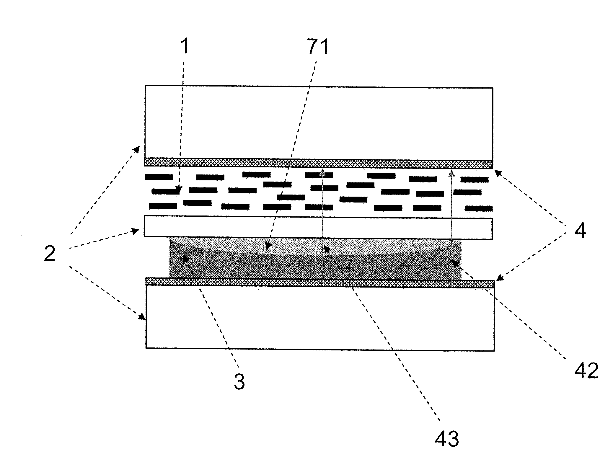
[0046] The present invention provides a method to generate a spatially non-uniform electric field by uniform electrodes and devices that use this method for controlling propagation of light. The devices of the present invention may be used for tunable focusing, diffracting, steering, etc.

[0047] For the sake of brevity, the following description will focus on simple refractive and diffractive structures, while other types of structures and more complex combinations of elements may equally be used. Similarly, embodiments using static or electro-optic materials will be described, it being understood that other materials may be used instead to obtain the same goal, which is low loss, high efficiency operation, and in some embodiments, a “no-action-at-0-voltage” property.

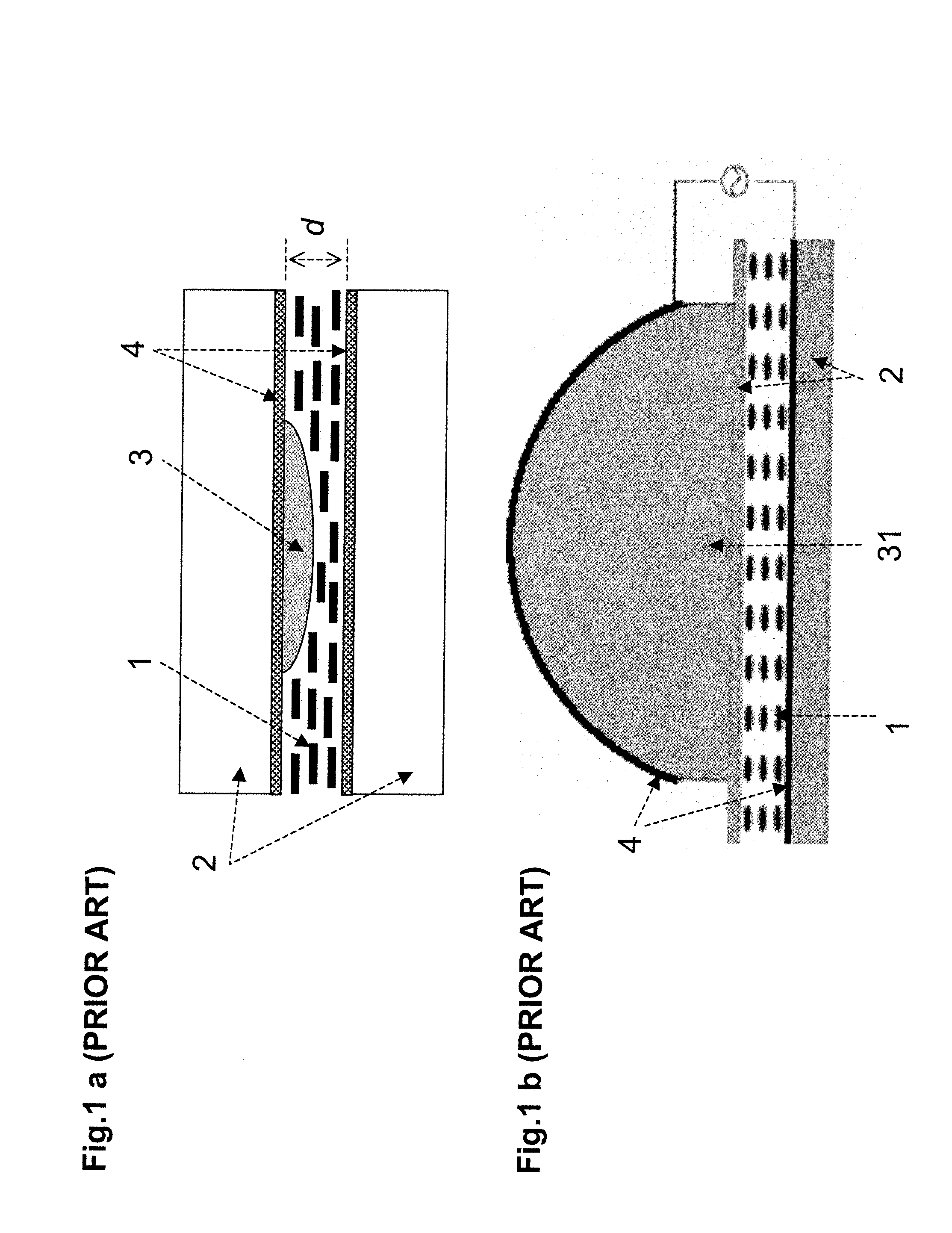
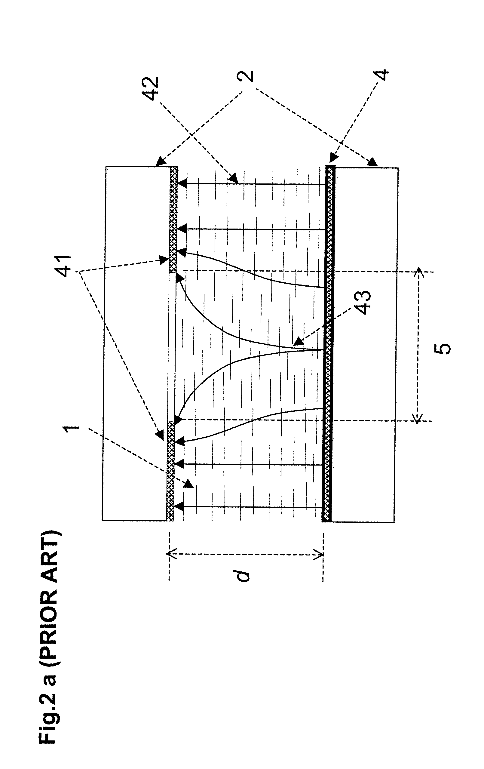
[0048] Referring to FIG. 1a, we show a prior art lens, where the LC (1) is sandwiched between two glass substrates (2) with transparent electrodes (4). A non-uniform profile element (3) is immersed in the LC layer to o...


PUM

PropertyMeasurementUnit
dielectric constantaaaaaaaaaa
diameteraaaaaaaaaa

Abstract

A variable optical device for controlling the propagation of light has a liquid crystal layer (1), electrodes (4) arranged to generate an electric field acting on the liquid crystal layer, and an electric field modulation layer (3,71) arranged between the electrodes and adjacent the liquid crystal layer for spatially modulating said electric field in a manner to control the propagation of light passing through said optical device. The electric field modulation layer has either an optical index of refraction that is essentially spatially uniform, or a polar liquid or gel, or a very high low frequency dielectric constant material having a dielectric constant greater than 20, and preferably greater than 1000. The modulation layer can have a solid body having a first low frequency dielectric constant with a shape selected to impart a desired modulation of the electric field, and a second low frequency dielectric constant material surrounding or adjacent to the solid body such that the solid body and the second material form a layer geometry.

Description

TECHNICAL FIELD [0001] The present invention relates to electrically controllable optical devices and, in particular, to a method and apparatus for creation of spatially non uniform electric field and its use in electro optical tuning of optical properties of refractive and diffractive optical elements using liquid crystals (LC). BACKGROUND OF THE INVENTION [0002] As is well known in the art, the successful implementation of intelligent (self-adjustable) optical imaging systems requires devices capable of controllably changing their optical properties. One of the most important optical functions required to be adjustable is the focusing capacity and the focusing distance. Those properties are essential, for example, for the manufacturing of high quality cell phone cameras, storage / reading systems, adjustable glass of contact and other vision systems. [0003] In modern high performance optical imaging systems the optical zoom is obtained by the use of a mechanical movement. This impli...

Claims


Application Information

Patent Timeline
Patent Type & Authority Applications(United States)
IPC IPC(8): G02F1/13
CPCG02B3/14G02B13/0075G02F2201/12G02F1/29G02F2001/294G02F1/1333G02F1/294G02F1/13G02F1/1335G02F1/133
Inventor GALSTIAN, TIGRANPRESNIAKOV, VLADIMIRASATRYAN, KAREN
Owner UNIV LAVAL
Why Eureka
Try Eureka