
Wavelength calibration in a fiber optic gyroscope

Active Publication Date: 2007-10-04
HONEYWELL INT INC
View PDF9 Cites 27 Cited by
  • Summary
  • Abstract
  • Description
  • Claims
  • Application Information

AI Technical Summary

Benefits of technology

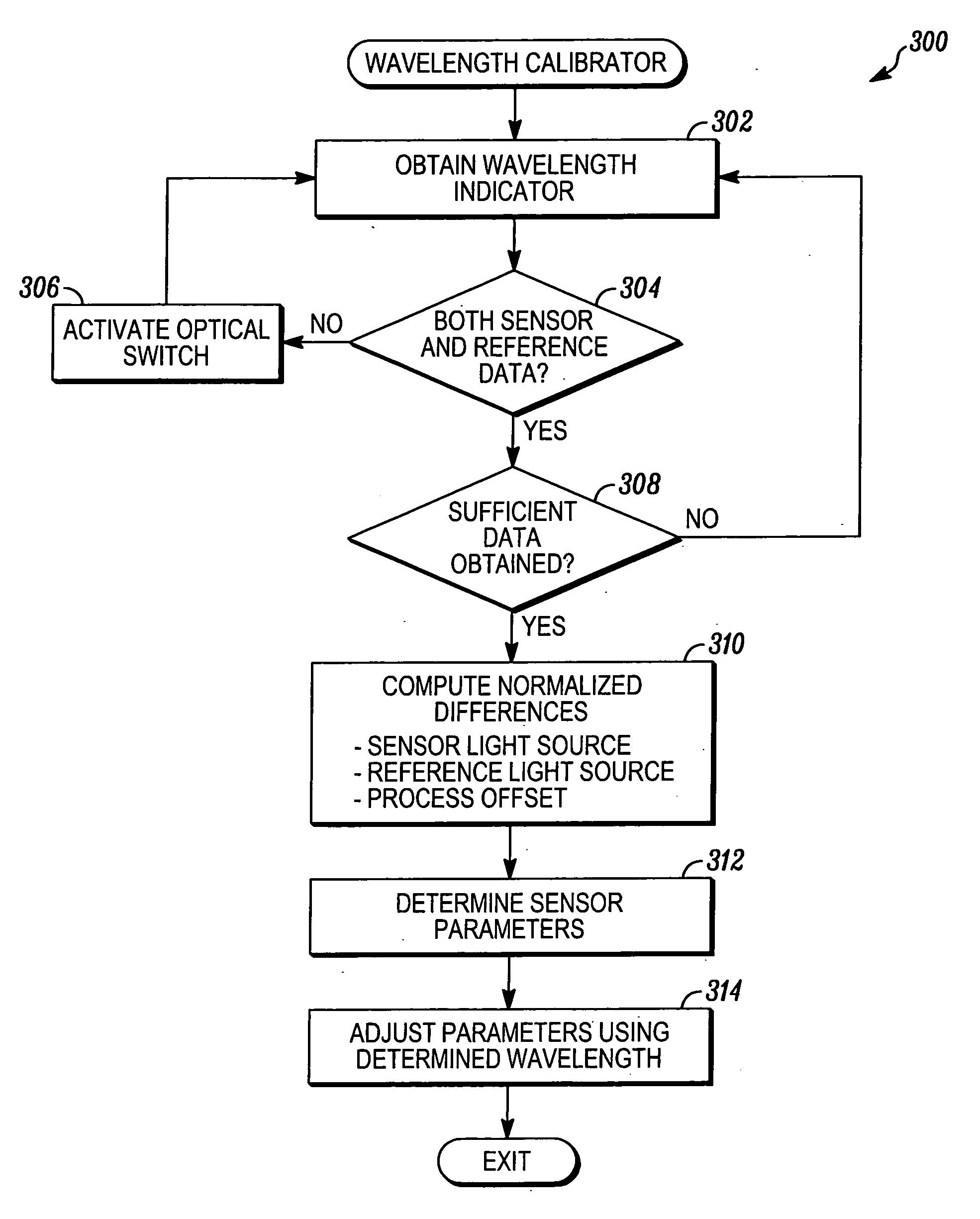
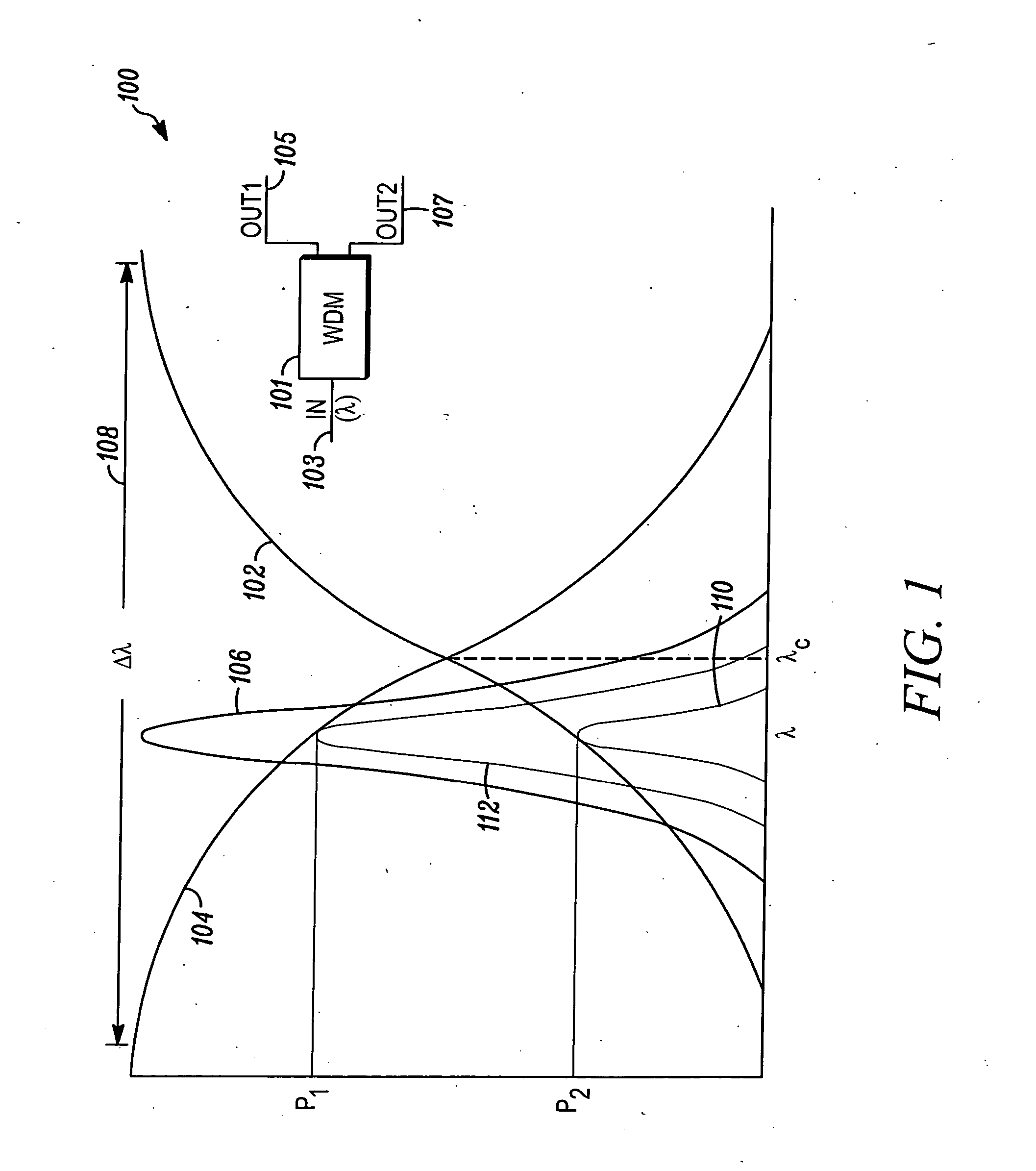
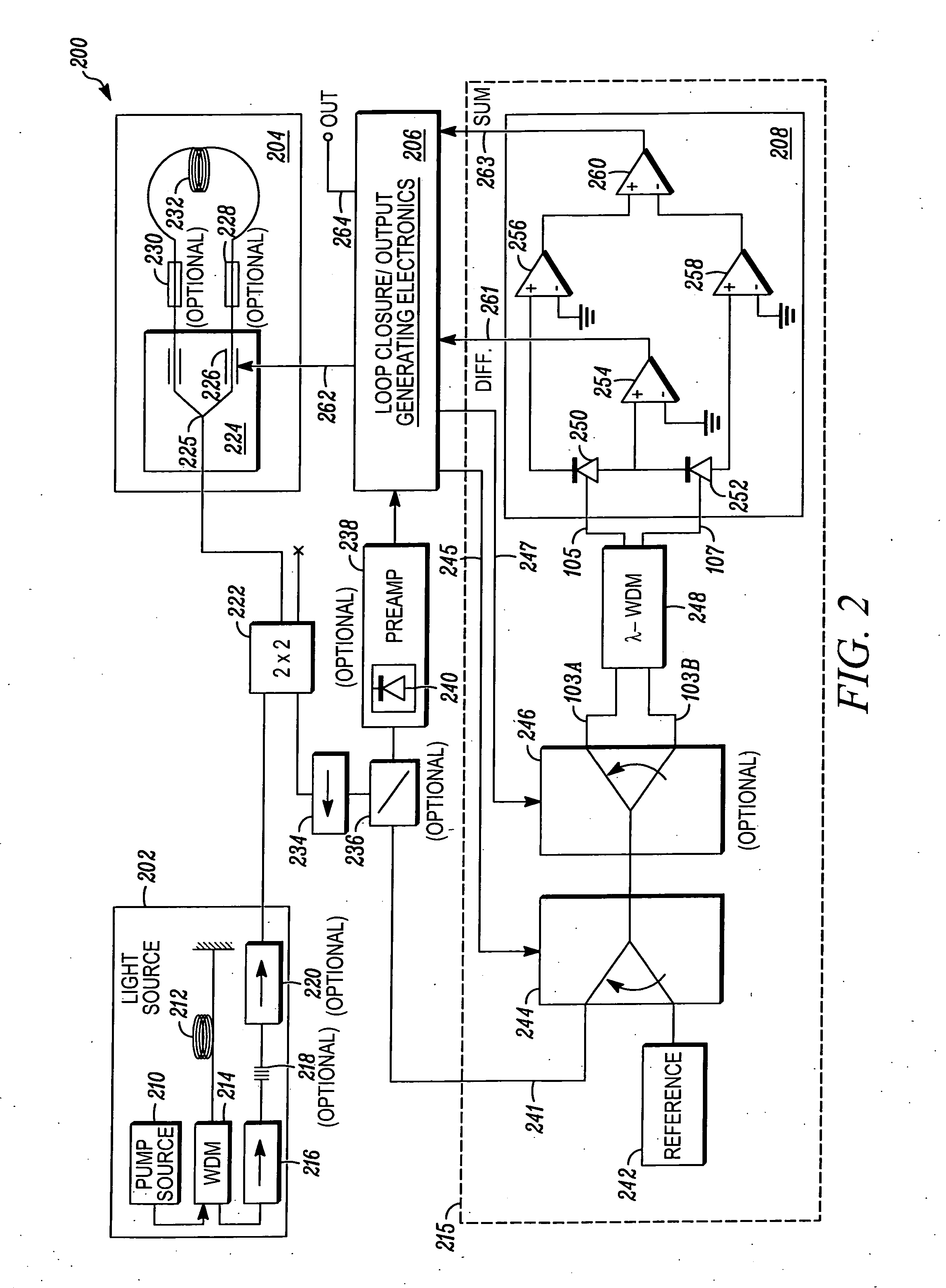
[0005] Methods and apparatus are provided for compensating the output of a fiber optic gyroscope in response to changes in source light wavelength. Changes in the source wavelength can be accurately measured using a reference source and wavelength division multiplexer, and the measured value can be used to adjust the scale factor or other operating parameter of the gyroscope during operation. Because these techniques seek to compensate the output of the gyroscope rather than to finely control the operation of the light source, the techniques described herein can be used to create optical sensors that are less complex and / or that have improved operating parameters in comparison to prior art sensors.

Problems solved by technology

Gyroscopes frequently operate in highly demanding environments (e.g. aerospace or battlefield settings) that can require very high levels of performance even in the face of radiation, extreme temperature variances, electromagnetic noise and / or other environmental effects.

Method used


Image

  • Wavelength calibration in a fiber optic gyroscope
  • Wavelength calibration in a fiber optic gyroscope
  • Wavelength calibration in a fiber optic gyroscope

Examples


Embodiment Construction

[0013] The following detailed description of the invention is merely exemplary in nature and is not intended to limit the invention or the application and uses of the invention. Furthermore, there is no intention to be bound by any theory presented in the preceding background of the invention or the following detailed description of the invention.

[0014] As noted above, the mean wavelength of light propagating in a fiber optic gyroscope (FOG) can change in response to temperature fluctuations, radiation and / or other environmental effects, thereby potentially causing error in the measured rate of rotation. FOGs have traditionally avoided wavelength fluctuations by carefully controlling the operation of the light source, a process that has typically been highly sensitive to the mean wavelength of optical sensors, as well as to the total light intensity of the light produced and to the responsivity of the photodiodes used in the gyroscope. In particular, some current gyroscope designs ...


PUM


Abstract

Methods and apparatus are provided for calibrating a fiber optic gyroscope (FOG) to compensate for wavelength fluctuations. The wavelength of the light propagating in the gyroscope is accurately determined by obtaining wavelength indicia for light originally produced by the sensor light source and for light produced by a reference light source. The wavelength indicia may include normalized power values, such as sum and difference indicia, obtained from two outputs of a wavelength division multiplexer. Such information can be used to determine the wavelength of light produced by the sensor light source, and to adjust a scale factor or other operating parameter of the gyroscope as a function of the determined wavelength. This adjustment, in turn, can be used to compensate the output of the sensor to account for wavelength variations.

Description

TECHNICAL FIELD [0001] The present invention generally relates to fiber optic gyroscopes, and more particularly relates to techniques and structures for compensating the output of a fiber optic gyroscope in response to wavelength variations. BACKGROUND [0002] For many years, fiber optic gyroscopes have been used in guidance and navigation systems for aircraft, satellites, missiles, watercraft and other moving objects. Fiber optic gyroscopes typically utilize two beams of light that rotate in opposite directions around a coil of optical fiber. As the coil rotates, the propagation of the light beams within the fiber varies according to the well-known Sagnac Effect. By sensing relative changes in the phase of the two counter-rotating light beams within the coil, then, the rotation of the coil itself can be detected with a very high level of accuracy. This rotation of the coil can be readily correlated to rotation of a vehicle, missile or other object. [0003] Gyroscopes frequently opera...

Claims


Application Information

Patent Timeline
IPC IPC(8): G01B9/02G01C19/64G01C19/72G01J3/45
CPCG01C19/721G01C19/64
Inventor GREENING, THOMAS C.ANSON, SCOTT A.
Owner HONEYWELL INT INC
Learn More