Multi-mode fluid cooling system and method

a fluid cooling and multi-mode technology, applied in the direction of cooling/ventilation/heating modification, semiconductor/solid-state device details, semiconductor devices, etc., can solve the problems of lower performance and higher wall temperature, and achieve high heat transport, high heat removal efficiency, and high heat removal efficiency

Active Publication Date: 2007-10-04
WISCONSIN ALUMNI RES FOUND
View PDF5 Cites 33 Cited by
  • Summary
  • Abstract
  • Description
  • Claims
  • Application Information

AI Technical Summary

Benefits of technology

[0014] The present invention provides a method and system for cooling electronic circuitry and other surfaces that employs a multi-mode fluid cooling process: evaporation of a significant portion of the fluid will increase heat removal efficiency, while single phase sensible heating will keep the heated surface wet to prevent dryout failure. The present invention employs a mixture of cooling fluids with different boiling points to cool electronic circuitry and other surfaces. By using such a mixture both high heat removal and high heat transport can be obtained.
[0015] Pool boiling and flow boiling experimental results for mixtures of refrigerants and glycol / water mixtures that are documented in the literature indicate that heat transfer decreases with the use of coolant mixtures, sometimes by as much as 100% or more. This is thought to be due to the stratification of the mixture during the boiling process. That is, a temperature gradient forms in the mixture, driving the more volatile liquid away from the heated surface. This layer of liquid rich in one component acts as a resistance to the transport of the other component to a vapor, resulting in higher wall temperatures and lower performance.
[0016] In contrast, in a accordance with the present invention, a mixture of cooling fluids is sprayed onto the surface to be cooled using conventional or other spray cooling systems or methods. The spray application process forces the cooling fluid to remain well mixed, eliminating the detrimental concentration gradients that occur in more traditional applications using a mixture of cooling fluids. Once the temperature of the mixture impinging on the surface being cooled reaches the bubble point of the mixture (the temperature at which vapor begins to form), additional heat is removed primarily by evaporation rather than raising the fluid temperature. This will significantly reduce temperature variations across the surface being cooled. The less volatile fluid in the cooling fluid mixture remains liquid. Keeping a liquid-phase component in contact with the surface being cooled at all times also reduces the temperature variations across the surface being cooled. By remaining a liquid, the less volatile component ensures that the surface being cooled remains wetted, preventing large, potentially damaging, temperature fluctuations on the surface being cooled. The presence of the evaporative component of the mixture, however, allows for the removal of more heat for a given flow rate than when using just a pure liquid coolant, because significantly more thermal energy can be stored per unit mass through phase change versus heating a liquid.
[0017] The present invention thus addresses three important limitations of current spray cooling applications for electronics: uniform heat transfer over a large area, drainage of the spray coolant after impacting the heated surface, and low critical heat flux (burnout) conditions. The use of a less volatile component in a cooling fluid mixture in accordance with the present invention will help keep the fluid temperature uniform over the heated surface. The volatile component of the mixture will allow greater heat removal with less fluid flow, facilitating the removal of the fluid from the heated surface and the use of smaller pumps and heat exchangers. Critical heat flux is increased significantly because the temperature of the cooling fluid contacting the surface to be cooled will be kept below the boiling point of the less volatile component of the mixture at much higher rates than in a single component cooling fluid due to the added heat removal by evaporation of the more volatile component of the mixture.

Problems solved by technology

This layer of liquid rich in one component acts as a resistance to the transport of the other component to a vapor, resulting in higher wall temperatures and lower performance.

Method used


Image

  • Multi-mode fluid cooling system and method
  • Multi-mode fluid cooling system and method
  • Multi-mode fluid cooling system and method

Examples


Embodiment Construction

[0026] The present invention will be described in detail herein with reference to the use thereof for the cooling of electronic circuits and electronic devices, particularly microelectronic circuitry as employed in computer systems, such as high-speed, high-performance computer systems (supercomputers). However, it should be understood that the present invention also may be applied in other applications, such as in the biomedical industry and for the cooling of laser arrays and high powered weaponry, etc. Spray evaporative cooling in accordance with the present invention may be applied to cryogenic devices, as an aid to laser-assisted surgical procedures, etc. It should also be understood that various combinations of cooling fluids other than those described herein may be used in a multi-mode cooling system and method in accordance with the present invention.

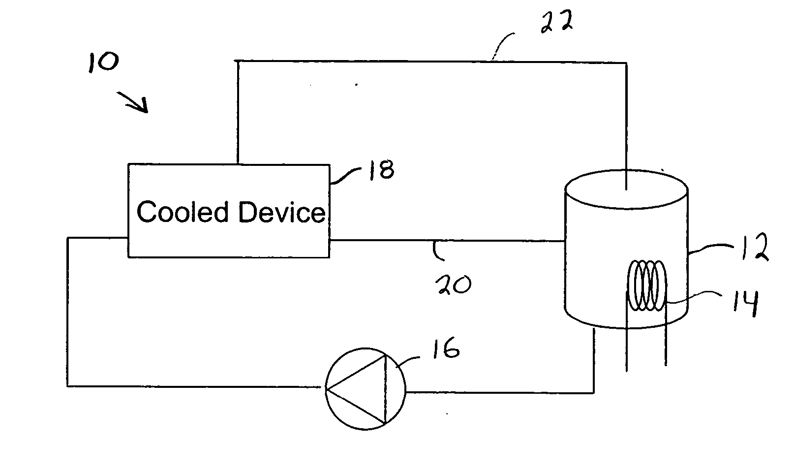
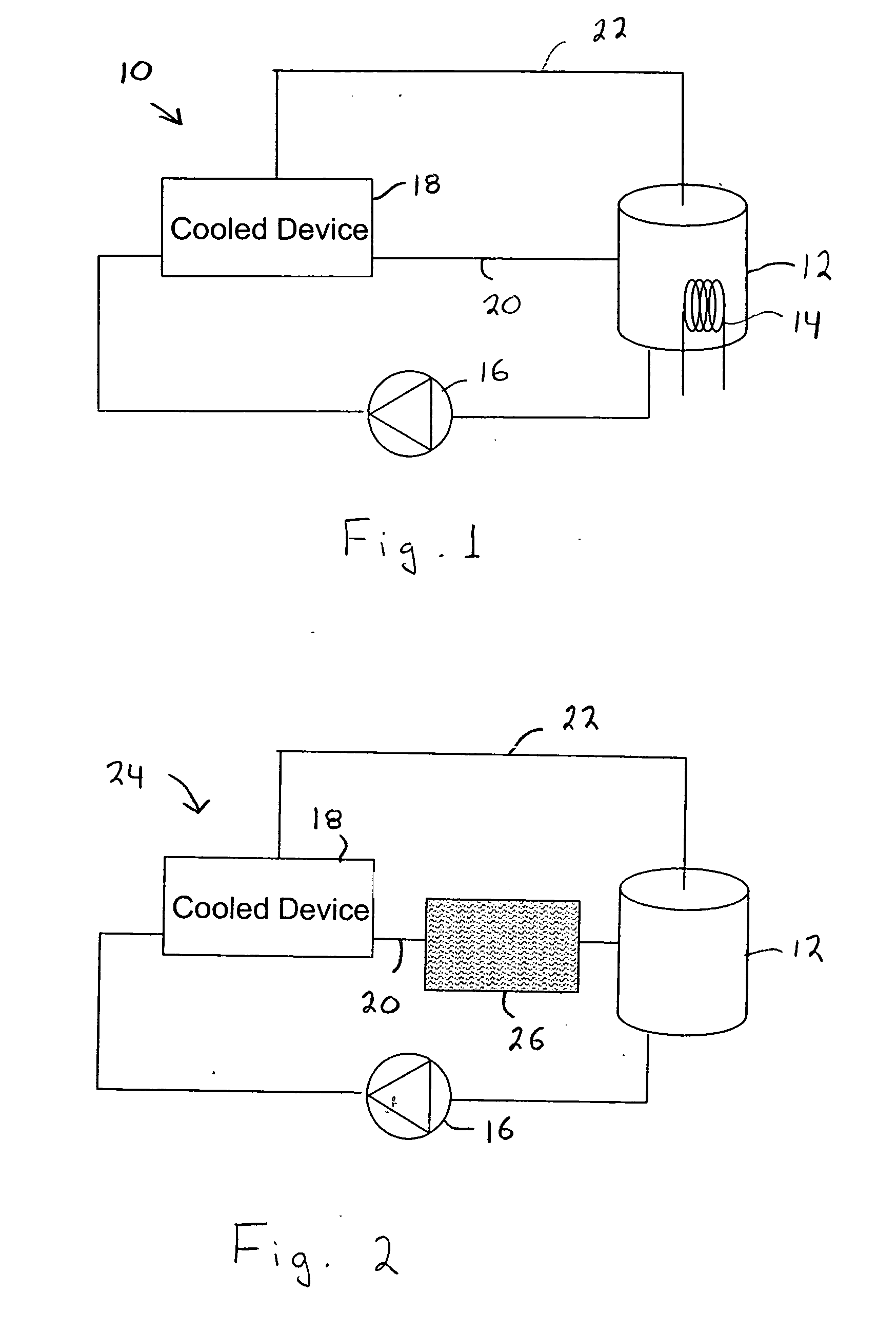
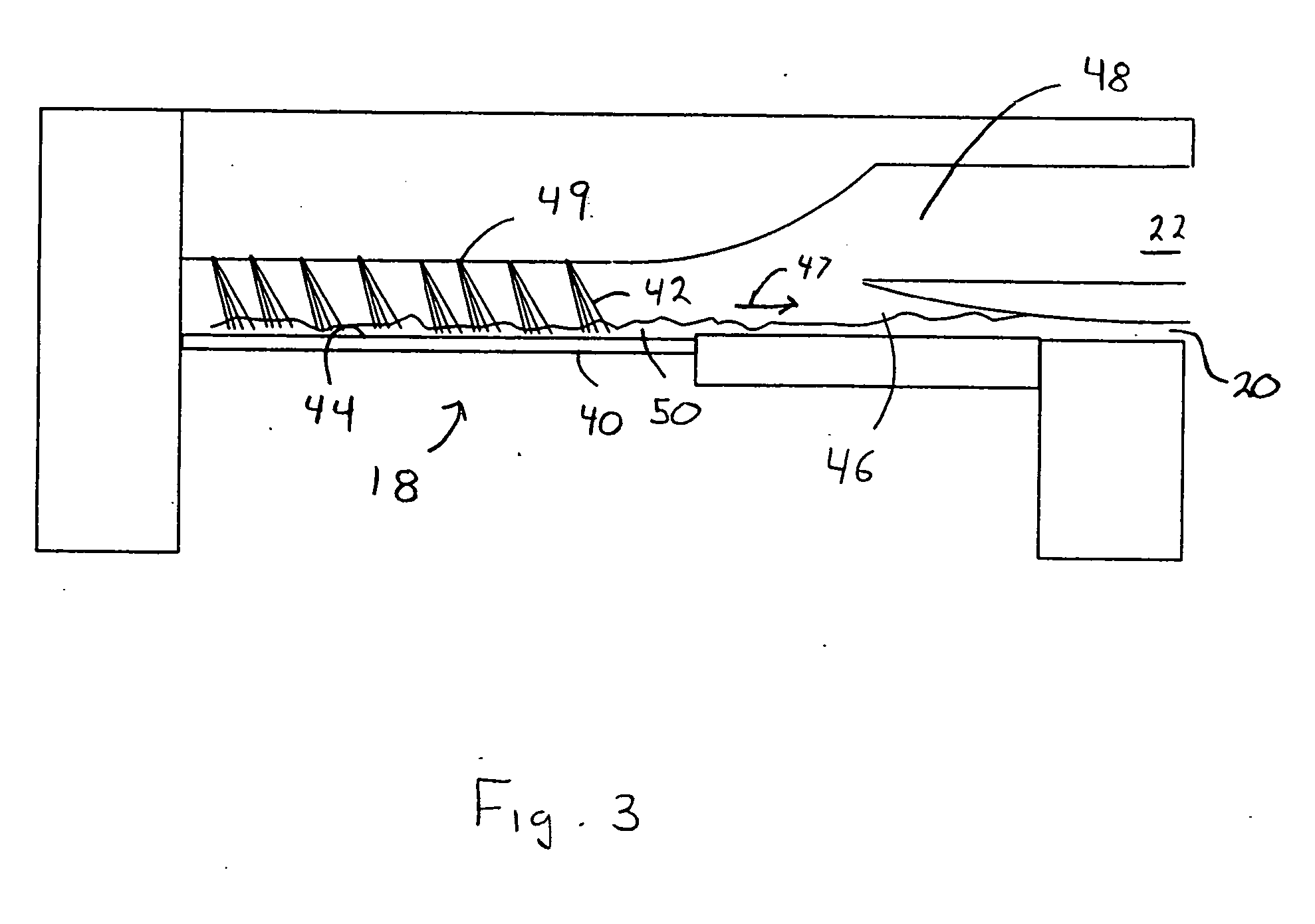
[0027] Multi-mode fluid cooling in accordance with the present invention is provided by spraying a cooling fluid mixture onto...


PUM

PropertyMeasurementUnit
angleaaaaaaaaaa
angleaaaaaaaaaa
distanceaaaaaaaaaa

Abstract

A cooling system and method that significantly improves spray evaporative cooling by using a mixture of cooling fluids having different boiling points. The cooling fluid mixture is sprayed onto a surface to be cooled. Efficient cooling with reduced cooling fluid volume is provided by both evaporation of the more volatile component of the mixture as well as heating of the less volatile component which remains in contact with the surface being cooled. More uniform temperatures across the surface being cooled and a reduced risk of potentially damaging critical heat flux is achieved.

Description

[0001] This invention was made with United States government support awarded by the following agencies: NSF 0134510. The United States has certain rights in this invention.FIELD OF THE INVENTION [0002] This invention pertains generally to cooling systems and methods employing cooling fluids and, more particularly to such systems and methods as used to cool electronic circuitry in high-performance computers and similar systems using spray evaporative cooling and similar systems and methods and to the cooling fluids used in such cooling systems and methods. BACKGROUND OF THE INVENTION [0003] Removal of heat from electronic circuitry has become one of the limiting factors in the design and performance of most computer systems and many other electronic devices. Power dissipation of a computer increases approximately as the operating frequency squared. Thus, doubling the clock speed, roughly doubling computer system performance, will require nearly four times the power dissipation. Curre...

Claims


Application Information

Patent Timeline
Patent Type & Authority Applications(United States)
IPC IPC(8): H05K7/20
CPCH01L23/4735H05K7/20345H01L2924/0002H01L2924/00
Inventor PAUTSCH, ADAM G.SHEDD, TIMOTHY A.
Owner WISCONSIN ALUMNI RES FOUND
Why Eureka
Try Eureka