Recording head and recorder

a recording head and recorder technology, applied in special recording techniques, instruments, nanoinformatics, etc., can solve the problems of not being able to achieve dramatic increases, requiring a high coercive force for recording media, and never allowing contact between a device to be heated and the recording medium

Inactive Publication Date: 2007-10-04
KONICA MINOLTA OPTO
View PDF11 Cites 18 Cited by
  • Summary
  • Abstract
  • Description
  • Claims
  • Application Information

AI Technical Summary

Benefits of technology

[0010] In view of the circumstance described above, the present invention has been made, and it is an object of the invention to provide a small-size recording head capable of high-density information recording on a small light spot and a recorder using such a recording head.

Problems solved by technology

In a magnetic recording method, a magnetic bit is remarkably susceptible, at high recording density, to the outside temperature and the like, thus requiring a recording medium having a high coercive force.
The magnetic field generated by the recording head has its upper limit determined by the saturation magnetic flux density, and this value is close to the material limit and thus cannot be expected to increase dramatically.
Moreover, contact between a device to be heated and the recording medium are never permitted.
To perform ultra high density recording by the optically assisted method, the required spot diameter is approximately 20 nm, but light cannot be condensed to such a size due to diffraction limitation imposed on a normal optical system.
Thus, the thickness of a magnetic recording head is limited.
The optically assisted magnetic recording head described in patent document 1 and a typical magneto-optic recording head (MO) have a large optical system arranged on the back surface thereof, and thus the magnetic recording head fails to support a magnetic recorder whose magnetic recording head described above is limited in thickness.
An optically assisted section in the optically assisted magnetic recording head needs to exist under the presence of a magnetic recording section and a magnetic reproduction section used in a typical hard disk device; thus, as described above, large NA causes light to interfere with the magnetic recording section and the magnetic reproduction section and also leads to upsizing of the beam diameter and the magnetic recording head.

Method used


Image

  • Recording head and recorder
  • Recording head and recorder
  • Recording head and recorder

Examples


Embodiment Construction

[0036] Hereinafter, an optically assisted magnetic recording head according to the present invention, a magnetic recorder provided therewith, and the like will be described, with reference to the accompanying drawings. Note that the same or corresponding portions among embodiments and the like are provided with the same numerals and thus their overlapping description will be omitted as appropriate.

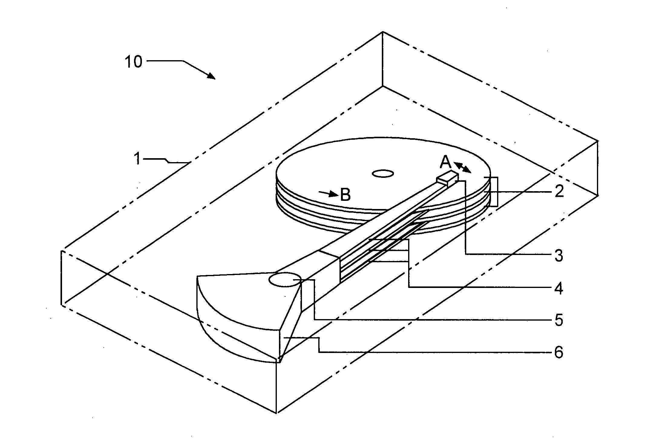
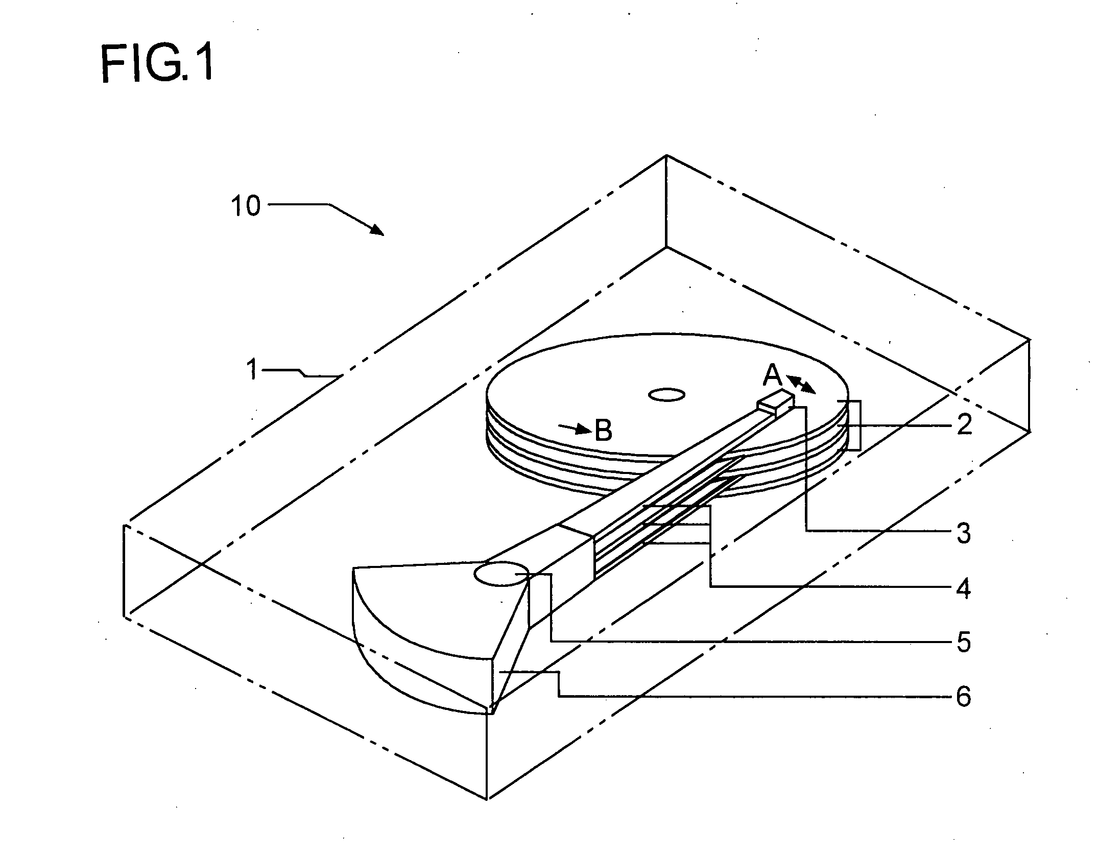
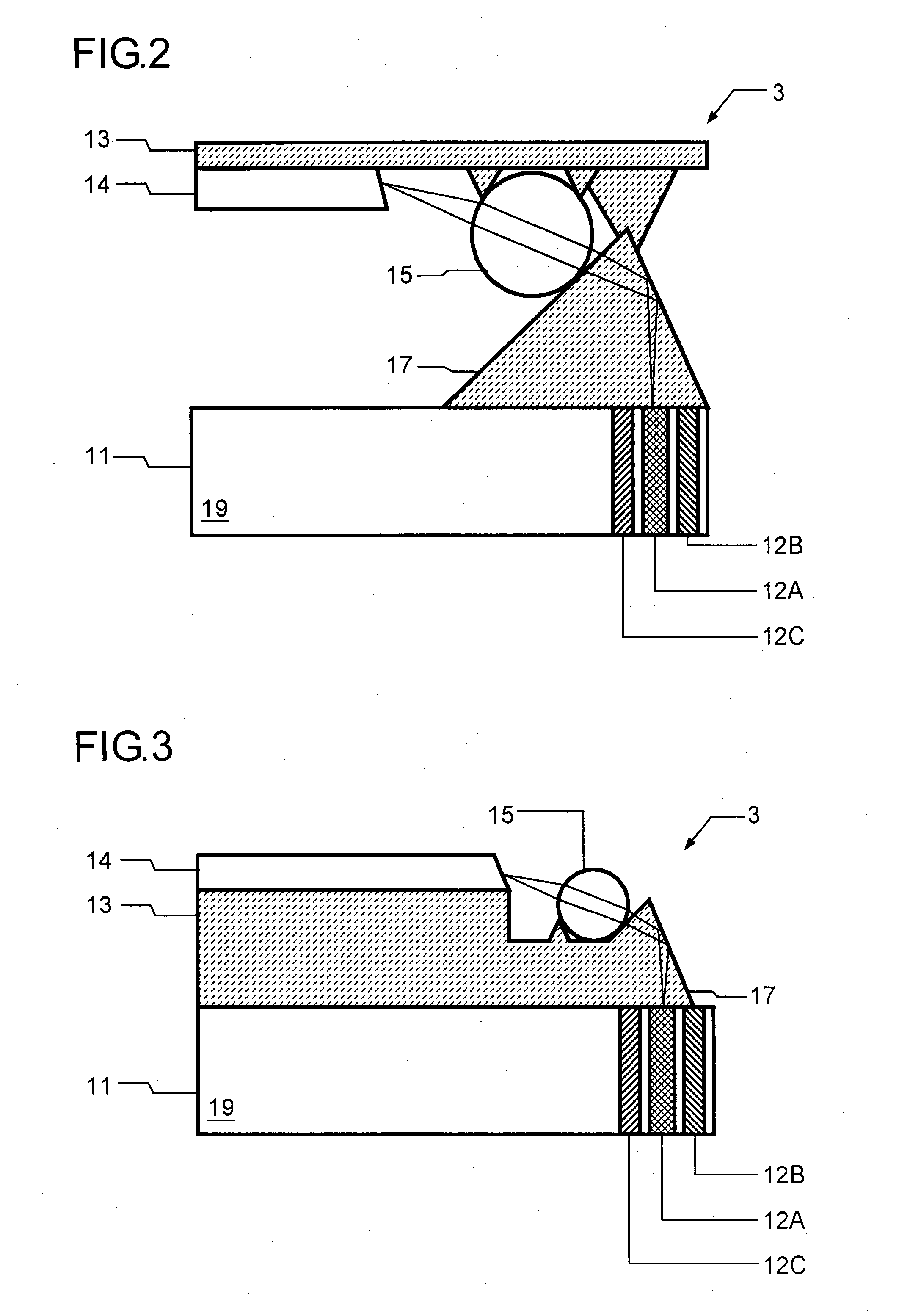
[0037]FIG. 1 shows an example of schematic configuration of a magnetic recorder (for example, hard disk device) loaded with an optically assisted magnetic recording head. This magnetic recorder 10 is so configured as to have in a case 1: a recording disk 2 (magnetic recording medium); a suspension 4 so provided as to be rotatable in a direction of an arrow A (tracking direction) about a spindle 5 as a supporting point; a tracking actuator 6 fitted to the suspension 4; an optically assisted magnetic recording head 3 fitted to the tip end section of the suspension 4; and a motor, not shown,...


PUM

PropertyMeasurementUnit
near-infrared wavelengthaaaaaaaaaa
diameteraaaaaaaaaa

Abstract

A recorder has a recording head which uses light for information recording to a recording medium. The recording head has a slider and an optical waveguide. The slider moves relative to the recording medium while floating thereon. The optical waveguide is provided in the slider and has a refractive index difference of 20% or more between a core and a cladding.

Description

[0001] This application is based on Japanese Patent Application No. 2006-068879 filed on Mar. 14, 2006, the contents of which are hereby incorporated by reference. BACKGROUND OF THE INVENTION [0002] 1. Field of the Invention [0003] The present invention relates to a recording head and a recorder, and, for example, to a micro-optical recording head which uses light for information recording and a micro-optical recorder using such a micro-optical recording head, and to an optically assisted magnetic recording head which uses a magnetic field and light for information recording and an optically assisted magnetic recorder using such an optically assisted magnetic recording head. [0004] 2. Description of Related Art [0005] In a magnetic recording method, a magnetic bit is remarkably susceptible, at high recording density, to the outside temperature and the like, thus requiring a recording medium having a high coercive force. Use of such a recording medium requires a large magnetic field ...

Claims


Application Information

Patent Timeline
Patent Type & Authority Applications(United States)
IPC IPC(8): G11B11/00G11B7/12G11B7/135
CPCB82Y10/00G11B5/02G11B5/314G11B7/122G11B7/124G11B7/1359G11B2005/0021G11B7/1384G11B7/1387G11B11/10532G11B11/10554G11B11/1058G11B2005/0005G11B7/1378
Inventor NISHIDA, NAOKIUEDA, HIROAKIKUISEKO, MANAMISEKINE, KOUJIROUKONNO, KENJIOKITSU, MASAHIROHATANO, HIROSHI
Owner KONICA MINOLTA OPTO
Why Eureka
Try Eureka