Medium, apparatus, and method of recording optical-information

a technology of optical information and recording medium, applied in the direction of data recording, recording/reproducing/erasing using optical interference patterns, instruments, etc., can solve the problems of insufficient follow-up accuracy, inability to shorten the search time, and inability to achieve the effect of practical use of the record-playback apparatus

Inactive Publication Date: 2007-10-04
KK TOSHIBA
View PDF5 Cites 16 Cited by
  • Summary
  • Abstract
  • Description
  • Claims
  • Application Information

AI Technical Summary

Benefits of technology

[0018]According to another aspect of the present invention, an optical-information recording apparatus includes a motor that rotates an optical-information recording medium; a light source that emits a beam; a generating unit that generates a recording beam that includes an information beam containing information and a reference beam, a first diffracted beam that is a servo beam, and a second diffracted beam that is the servo beam, from the beam emitted from the light source; a condenser that focuses the information beam and the reference beam on an optical-information recording medium, focuses the first diffracted beam on a following up servo area, and focuses the second diffracted beam on an address servo area, the optical-information recording medium being included: a substrate that includes a servo surface having a servo pattern thereon, an information recording layer laminated on the servo surface of the substrate capable of recording information as a hologram produced by interference between an information beam containing the information and a reference beam, the address servo area that is formed as a part of the servo pattern in a track direction on the servo surface, and that records therein address information and clock information for aligning the beam to a target position in the information recording layer, and the following up servo area that is formed as a part of the servo pattern in the track direction on the servo surface, and that is to be irradiated by the beam so as to make the beam follow a rotation of the optical-information recording medium, wherein the address servo area and the following up servo area are arranged in parallel extending in circumferential direction on the optical-information recording medium; a servo photodetector that detects a first reflection of the first diffracted beam reflected from the following up servo area and a second reflection of the second diffracted beam reflected from the address servo area; an irradiation-position shifting unit that shifts irradiation positions of the first diffracted beam and the second diffracted beam on the optical-information recording medium by moving the condenser; and a following up control unit that performs following-up servo control to control the irradiation-position shifting unit based on the first reflection by shifting the irradiation positions of the first diffracted beam, the second diffracted beam, and the recording beam to follow rotation of the optical-information recording medium so that relative velocity between the optical-information recording medium and the irradiation positions is substantially zero, and that records the information during the following-up servo control.
[0019]According to still another aspect of the present invention, an optical-information recording method includes rotating an optical-information recording medium; emitting a beam from a light source; generating a recording beam that includes an information beam containing information and a reference beam, a first diffracted beam that is a servo beam, and a second diffracted beam that is the servo beam, from the beam emitted from the light source; focusing the information beam and the reference beam on an optical-information recording medium; focusing the first diffracted beam on a following up servo area; focusing the second diffracted beam on an address servo area, the optical-information recording medium being included: a substrate that includes a servo surface having a servo pattern thereon, an information recording layer laminated on the servo surface of the substrate capable of recording information as a hologram produced by interference between an information beam containing the information and a reference beam, the address servo area that is formed as a part of the servo pattern in a track direction on the servo surface, and that records therein address information and clock information for aligning the beam to a target position in the information recording layer, and the following up servo area that is formed as a part of the servo pattern in the track direction on the servo surface, and that is to be irradiated by the beam so as to make the beam follow a rotation of the optical-information recording medium, wherein the address servo area and the following up servo area are arranged in parallel extending in circumferential direction on the optical-information recording medium; detecting a first reflection of the first diffracted beam reflected from the following up servo area and a second reflection of the second diffracted beam reflected from the address servo area; shifting irradiation positions of the first diffracted beam and the second diffracted beam on the optical-information recording medium by moving the condenser; performing following-up servo control based on the first reflection by shifting the irradiation positions of the first diffracted beam, the second diffracted beam, and the recording beam to follow rotation of the optical-information recording medium so that relative velocity between the optical-information recording medium and the irradiation positions is substantially zero; and recording the information during the following-up servo control.

Problems solved by technology

More specifically, when the conventional technology is used, the record—playback apparatus for the holographic-optical-disk cannot rotate the disk at a high speed at the time of recording, thereby an overhead time is required for shifting from the recording operation to the playing back operation, and seek time cannot be shortened.
The displacement during the exposure is a very serious problem in the system architecture because the holographic recording includes writing fine refractive-index modulation using the photosensitive material that has a high spatial resolution.
As a result, the following up is not accurate enough to put the record-playback apparatus to practical use.
Moreover, because the relative velocity of the recording beam to the optical disk becomes zero during the following up, it is difficult to perform an accurate tracking servo control.
It is therefore difficult to perform an accurate positioning of the recording beam to the target recording position.

Method used


Image

  • Medium, apparatus, and method of recording optical-information
  • Medium, apparatus, and method of recording optical-information
  • Medium, apparatus, and method of recording optical-information

Examples


first embodiment

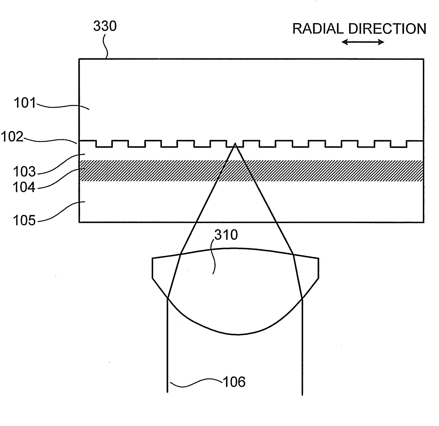
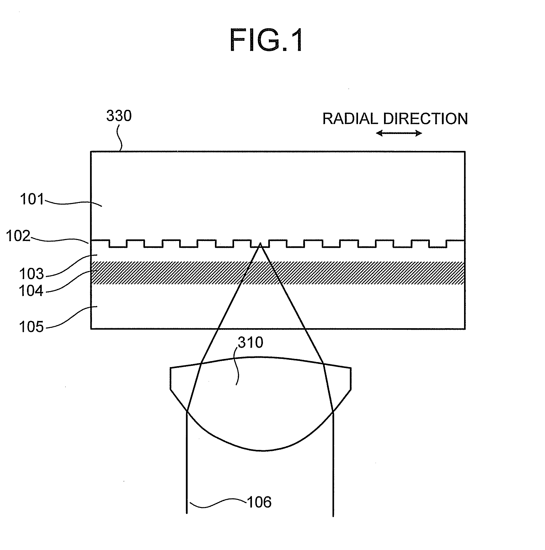
[0041]Exemplary embodiments of the present invention are explained below in detail referring to the accompanying drawings. The present invention is not limited to the embodiments explained below. FIG. 1 is a cross sectional view of a holographic optical disk 330 according to a The holographic-optical-disk 330 includes a polycarbonate substrate 101, a transparent gap layer 103, a holographic-recording medium layer 104 in which information is recorded, and a protective layer 105 that protects the holographic-recording medium layer 104, layered in the order. The holographic-optical-disk 330 further includes a servo surface 102 formed on a surface of the substrate 101 that faces the holographic-recording medium layer 104, and the servo surface 102 includes guiding grooves or ridges (hereinafter, abbreviated as “patterns”) or pits for focusing servo control, tracking servo control, and following-up servo control formed thereon. The state shown in FIG. 1 is that an objective lens 310 foc...

second embodiment

[0118]FIG. 16 is a schematic view for explaining a configuration of an optical system in a record-playback apparatus for holographic-optical-disk according to a

[0119]The configuration of the holographic-optical-disk used by the record-playback apparatus according to the second embodiment is identical to that of the holographic-optical-disk according to the first embodiment.

[0120]The record-playback apparatus for holographic-optical-disk according to the second embodiment uses the collinear holographic recording method as with the first embodiment, where the information beam and the reference beam are coaxially arranged.

[0121]The optical system in the record-playback apparatus for holographic-optical-disk according to the second embodiment includes the semiconductor laser 301, the collimating lens 302, the diffraction grating 303 as the resonator, a spatial light modulator 1604, the spatial filter 327b, a spatial filter 327c, the diffraction grating 316, the polarization beam splitte...

third embodiment

[0133]The record-playback apparatus performs tracking servo control by the DPD method while following-up servo control is not performed, and performs tracking servo control using the signal intensity of the reflection from the following-up pit row 203 during following-up servo control.

[0134]During following-up servo control, two signals from each beam spot on the adjacent sectional acceptance surfaces 704c and 704d are input to the differential amplifier 722 in the tracking control unit 603. The differential amplifier 722 computes the difference between the two signals, and the resulting differential signal 708 is output as the tracking error signal.

[0135]The record-playback apparatus according to the third embodiment does not use the differential signal of two trace signals for the following reason. As shown in FIG. 10, when the servo beam 502 is misaligned, the light intensities of the reflections on the adjacent two sectional acceptance surfaces are different. Therefore, the rec...


PUM

PropertyMeasurementUnit
shift distanceaaaaaaaaaa
distanceaaaaaaaaaa
poweraaaaaaaaaa

Abstract

An optical-information recording medium includes a substrate that includes a servo surface having a servo pattern thereon; an information recording layer laminated on the servo surface of the substrate capable of recording information as a hologram produced by interference between an information beam containing the information and a reference beam; an address servo area that is formed as a part of the servo pattern, and that records therein address information and clock information for aligning a beam, emitted from an optical-information recording apparatus for recording information in the information recording layer, to a target position in the information recording layer; and a following up servo area that is formed as a part of the servo pattern, and that is to be irradiated by the beam to make the beam follow a rotation of the optical-information recording medium.

Description

CROSS-REFERENCE TO RELATED APPLICATIONS[0001]This application is based upon and claims the benefit of priority from the prior Japanese Patent Application No. 2006-89280, filed on Mar. 28, 2006; the entire contents of which are incorporated herein by reference.BACKGROUND OF THE INVENTION[0002]1. Field of the Invention[0003]The present invention relates to an optical information recording medium, an optical information recording apparatus and an optical information recording method for recording information as hologram.[0004]2. Description of the Related Art[0005]High-density stacked-volumetric optical disks using holography (hereinafter, “holographic-optical-disks”) and record-playback apparatus for the holographic-optical-disks have been actively developed for practical use. The holographic-optical-disks record information by interfering an information beam that includes an image to be recorded with a reference beam for recording the image in a photosensitive material, and records a...

Claims


Application Information

Patent Timeline
Patent Type & Authority Applications(United States)
IPC IPC(8): G11B7/00G11B7/24G11B7/24035G11B7/24044G11B7/24085G11B7/24088G11B7/24091
CPCG11B7/0065G11B7/00781G11B7/24085G11B7/24044G11B7/2405G11B7/083
Inventor YAMAMOTO, YUICHIROTATSUTA, SHINICHIKUBOTA, YUJIHIRAO, AKIKOMATSUMOTO, KAZUKI
Owner KK TOSHIBA
Why Eureka
Try Eureka