

All-optical polarization rotation switch using a loop configuration
a technology of polarization-maintaining fibers and rotation switches, which is applied in the direction of optics, instruments, optical light guides, etc., can solve the problems of pm-fibers (polarization-maintaining fibers) not being suitabl
- Summary
- Abstract
- Description
- Claims
- Application Information
AI Technical Summary
Problems solved by technology
Method used
Image

Examples
embodiment i
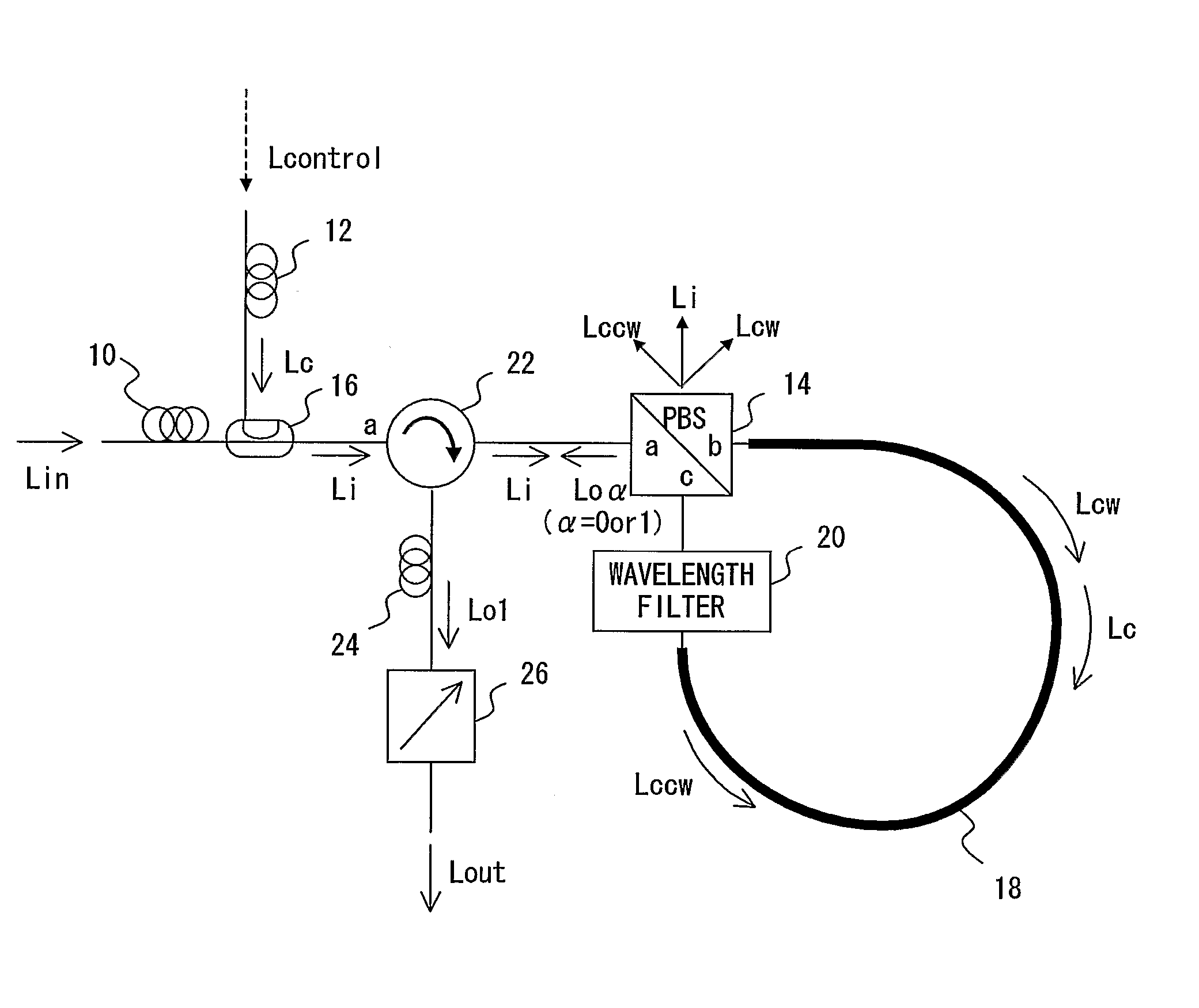
[0025]FIG. 3 is a schematic block diagram showing an exemplary arrangement of an all-optical polarization rotation switch in accordance with a first illustrative embodiment of the invention. In FIG. 3, the all-optical polarization rotation switch 1 comprises a polarization controller (PC) 10 that receives and linearly polarizes an input probe light from the external; a PC 12 that receives and linearly polarizes a control pump light or pulse Lcontrol from the external into a linearly polarized control pump light Lc; a polarization beam splitter (PBS) 14 having its port 14a is optically coupled with the PC 10; a directional coupler 16 which passes the split light output from a port 14b of the PBS 14 and couples the light received from a port 16c to a port 16b to which the passed split light is also coupled; a wavelength control filter 20 inserted just in front of a port 14c of the PBS 14; and a nonlinear fiber 18 in a loop configuration which optically connects a port 16b of the direc...
embodiment 1
Modifications of Embodiment 1
[0034]FIGS. 7 through 10 are schematic block diagrams showing exemplary arrangements of modifications of the all-optical polarization rotation switch of FIG. 3. In the following modifications, the directional coupler 16 for the pump light Lc is placed in front of the loop 18 instead inside the loop 18.
[0035] In FIG. 7, an all-optical polarization rotation switch 1a is identical to that of FIG. 3 except that the directional coupler 16 has been moved from the side 14b of the PBS 14 to between the optical circulator 22 and the PBS 14. The operation of the switch la is identical of that of FIG. 3 except that the linearly polarized control pump light Lc is coupled to the light path leading to the PBS port 14a.
[0036] In the same way, in FIG. 8, an all-optical polarization rotation switch 1b is identical to that of FIG. 3 except that the directional coupler 16 has been moved from the side 14b of the PBS 14 to between the PC 10 and the optical circulator 22. T...
embodiment ii
[0039]FIG. 11 is a schematic block diagram showing an exemplary arrangement of an all-optical polarization rotation switch in accordance with a second illustrative embodiment of the invention. In FIG. 11, the all-optical polarization rotation switch 2 is identical to that (1) of FIG. 3 except that [0040] (1) the optical circulator 22 has been replaced with a PBS 30 with its eigenaxis collinear with the input probe light (Li) polarization; [0041] (2) the optical circulator 24 and the polarizer 26 has been removed from the switch 1; [0042] (3) an isolator 32 has been inserted between the CP 10 and the PBS 30.
[0043] The isolator 32 blocks the component of the backward propagating output probe light Lo0 that is not rotated. The orthogonal component of the rotated light Lo1 is coupled to the second port 30c of PBS 30.
[0044]FIGS. 12 and 13 are schematic block diagrams showing exemplary arrangements of modifications of the all-optical polarization rotation switch 2 of FIG. 11.
[0045] In ...
PUM
 Abstract
Description
Claims
Application Information