Self-Cleaning Well Control Fluid

a well control fluid and self-cleaning technology, applied in the direction of fluid removal, wellbore/well accessories, chemistry apparatus and processes, etc., can solve the problems of not being able to remove all of the fluid or all of the solids, and affecting the operation of the well

Active Publication Date: 2007-10-11
SCHLUMBERGER TECH CORP
View PDF40 Cites 29 Cited by
  • Summary
  • Abstract
  • Description
  • Claims
  • Application Information

AI Technical Summary

Benefits of technology

[0007] In another embodiment, the slurry also contains a dissolvable second solid capable of accelerating the decomposition of the decomposable first solid. The dissolvable second solid may be a pH control agent and / or a fluid loss additive.

Problems solved by technology

One of the serious drawbacks to viscosifying a kill fluid or including fluid loss additives, is that one or both of these features may damage the well, the fracture, or the formation.
It may be difficult or impossible to remove all of the fluid or all of the solids, especially if some of the fluid and / or some of the solids invade the fracture or the formation.
Also, after some methods of downhole completion (for example after installation of an ESP) remedial treatments are not possible
Sometimes the operator may rely on the flow of produced fluids, but this method requires fluid flow and often results in slow or incomplete solids removal.
Sometimes a breaker can be incorporated in the well control fluid but these must normally be delayed (for example by esterification or encapsulation) and they are often expensive and / or difficult to place and / or difficult to trigger.

Method used


Image

  • Self-Cleaning Well Control Fluid
  • Self-Cleaning Well Control Fluid
  • Self-Cleaning Well Control Fluid

Examples


example 1

[0045] Experiments were run using a viscoelastic surfactant concentrate containing about 38% by weight erucic amidopropyl dimethyl betaine, about 23% isopropanol, about 5% sodium chloride, about 1% sodium naphthalene sulfonate, and the remainder water. As an example of a decomposable first solid, polylactic acid fibers were used. The fibers contained 12% water and 1% sizing. They had a denier of about 1.4 and were about 6 mm long.

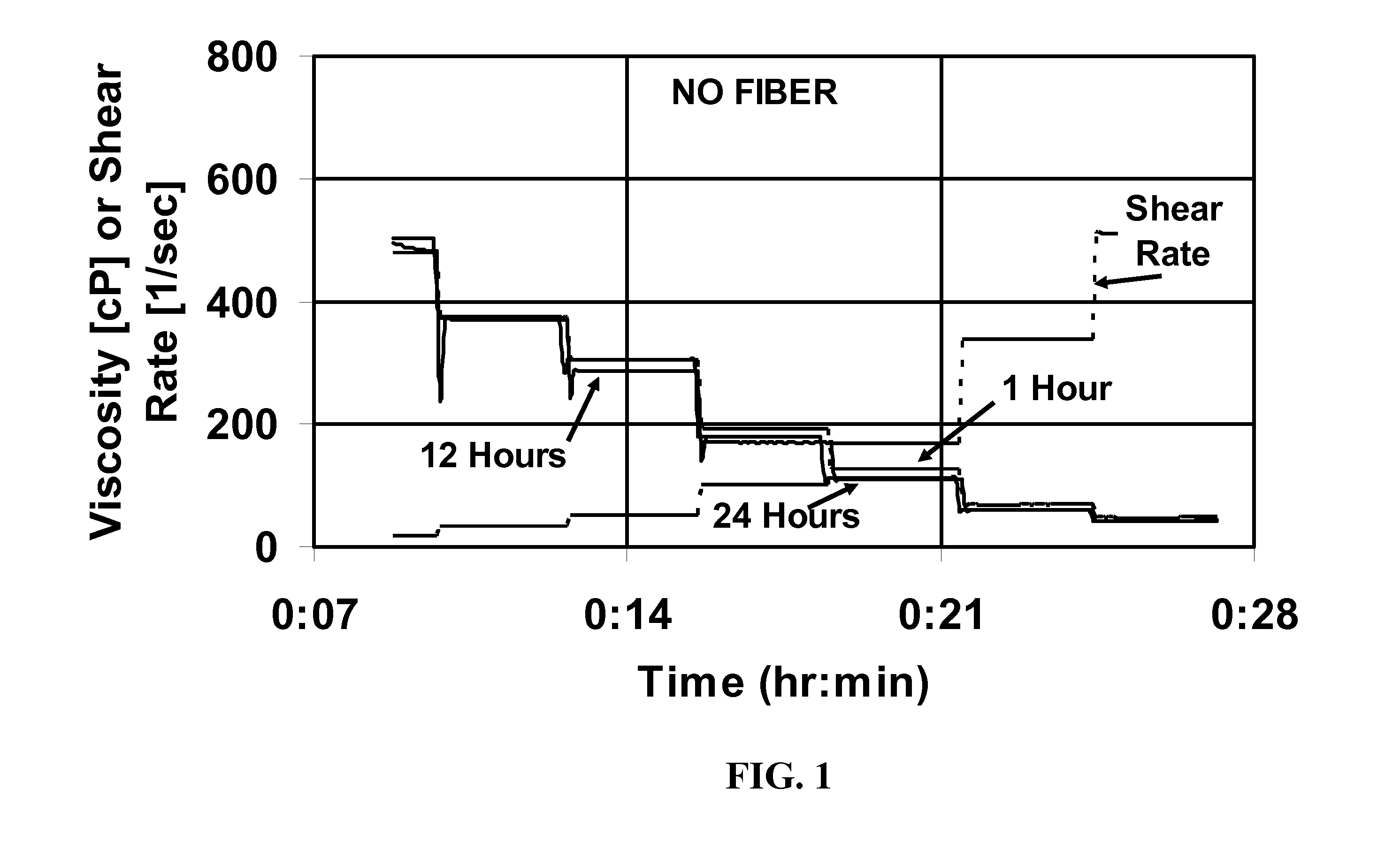
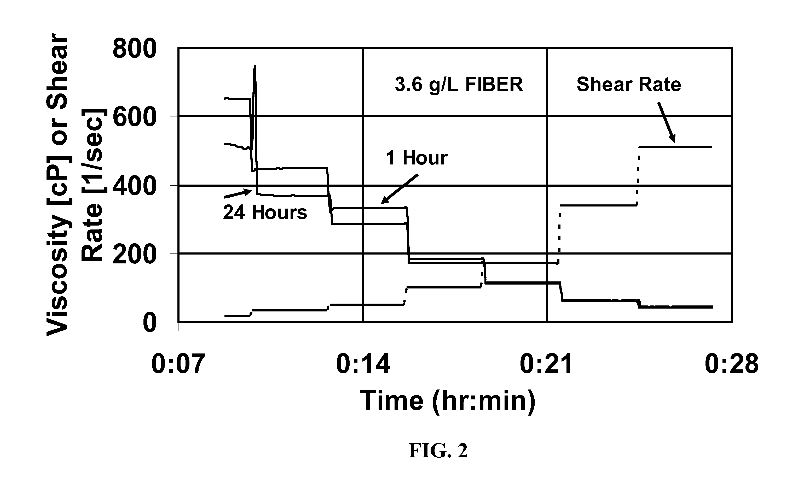
[0046]FIG. 1 shows the viscosity at various shear rates of a fluid made by adding 8 weight % of this surfactant concentrate to water, and then maintaining the fluid at 93° C. for up to one day. FIG. 2 shows a similar experiment, except that 3.6 g / L of the fiber was added. It can be seen that in these experiments, the fiber had very little effect on the viscosity at shear rates from 17 to 511 sec−1 and at times from 1 to 24 hours. This system would be stable for well control at this temperature fort at least one day. The fiber was visible in the system at t...

example 2

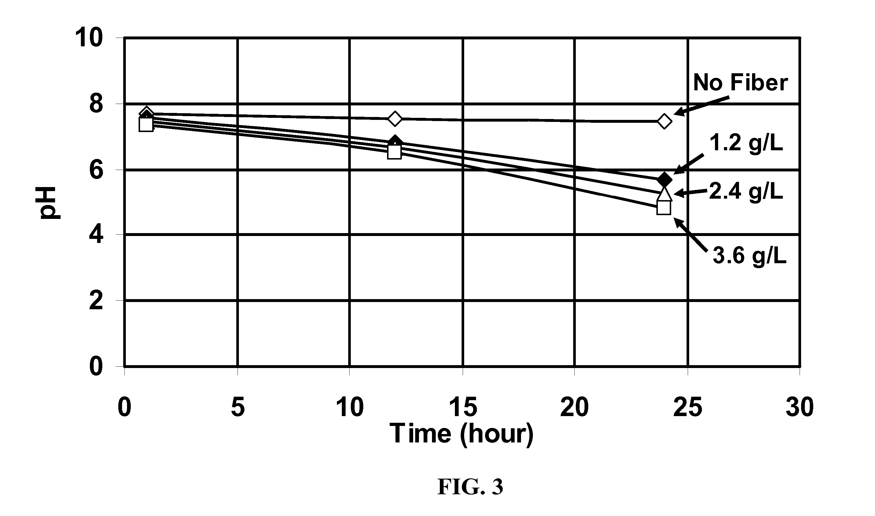
[0047] Additional experiments were run with 1.2 g / L fiber and 2.4 g / L fiber. FIG. 3 shows the pH as a function of time at 93° C. for the four runs. The pH steadily decreased with time when the fiber was present, and the more fiber, the greater the decrease. This shows that the polylactic acid was very slowly decomposing, and if the experiments had been continued, the gels would have broken, because it is known that these gels are broken (and the hydrolysis of the surfactants accelerated) by strong acid or by the addition of sufficient organic acid.

example 3

[0048] A fluid was made by adding 4% of the same surfactant concentrate used above, 7% KCl, varying amounts of solid sodium carbonate, 1.1 g (3.6 g / L) of the same fiber as used above, and a 2.5 cm (1 inch) long solid fiber plug (made from the same fiber), to 300 ml water. The physical appearances of the solid fiber plug and fluid were then monitored over time. FIG. 4 shows the days to 100% disappearance of the solid fiber plug at different initial solid sodium carbonate contents. It can be seen that the degradation of decomposable first solid (solid fiber material in plug form in this case) can be controlled this way over the range of from 1 to 10 days. FIG. 5 shows the same data as FIG. 4 but expressed as the days the plug survived vs. the initial amount of solid sodium carbonate present. The final pH in these fluids ranged from about 9.8 (with high initial solid sodium carbonate) to about 8.7 (with low initial solid sodium carbonate).


PUM

PropertyMeasurementUnit
viscosityaaaaaaaaaa
viscosityaaaaaaaaaa
melting pointaaaaaaaaaa

Abstract

A composition and method is given for a well control fluid that is injected into a well during completion or remediation and prevents fluid flow from a formation into the well during operations (such as shut-in, or placement or adjustment of tools/hardware) when no fluid flow is desired. The composition includes a viscoelastic surfactant fluid system (VES) and a decomposable first solid material, preferably in fiber form, that forms a pack or plug in the well at the location where fluid would otherwise leak off, and then decomposes without intervention to release a product that is a breaker for the surfactant or the micelles of the VES. The composition optionally also contains a pH control agent and a second solid (that may also be a fluid loss agent) that affect the decomposition of the first solid.

Description

BACKGROUND OF THE INVENTION [0001] The Invention relates to completing wells drilled into subterranean formations. More particularly it relates to methods of killing a well, that is preventing fluid from flowing from the formation into the wellbore, during completion or remediation. Most particularly, it relates to killing a well without damaging it, that is without decreasing subsequent production, especially after hydraulic fracturing while a well is being prepared for production. [0002] There are many wellbore operations in which it is necessary to allow a well to be in fluid communication with the formation it penetrates for a period of time under conditions where fluid could flow between the formation and the well unless steps were taken to prevent this. For example, after hydraulic fracturing, matrix acidizing or acid fracturing, frac packing, or gravel packing is completed it might be several days before appropriate hardware is installed in the next step of the completion (fo...

Claims


Application Information

Patent Timeline
Patent Type & Authority Applications(United States)
IPC IPC(8): C09K8/00E21B43/00
CPCC09K2208/30C09K8/74
Inventor FU, DIANKUIRUSSELL, STEVESAMUEL, MATHEW
Owner SCHLUMBERGER TECH CORP
Why Eureka
Try Eureka