High frequency array ultrasound system

a high-frequency array and ultrasound technology, applied in the field of high-frequency array ultrasound systems, can solve the problems of system inadequacies for imaging with higher resolution, and the inability to meet the requirements of small animal imaging applications

Active Publication Date: 2007-10-11
SUNNYBROOK HEALTH SCI CENT +1
View PDF93 Cites 159 Cited by
  • Summary
  • Abstract
  • Description
  • Claims
  • Application Information

AI Technical Summary

Benefits of technology

[0007] Additional advantages of the invention will be set forth in part in the description which follows, and in part will be obvious from the description, or may be learned by practice of the invention. The advantages of the invention will be realized and attained by means of the elements and combinations particularly pointed out in the appended claims. It is to be understood that both the foregoing general description and the following detailed description are exemplary and explanatory only and are not restrictive of the invention, as claimed.

Problems solved by technology

With these low operating frequencies, however, such systems are not appropriate for imaging where higher resolutions are needed, for example in imaging small animals such as mice or small tissue structures in humans.
Moreover, small animal imaging applications present several challenging requirements which are not met by currently available imaging systems.

Method used


Image

  • High frequency array ultrasound system
  • High frequency array ultrasound system
  • High frequency array ultrasound system

Examples


example 1

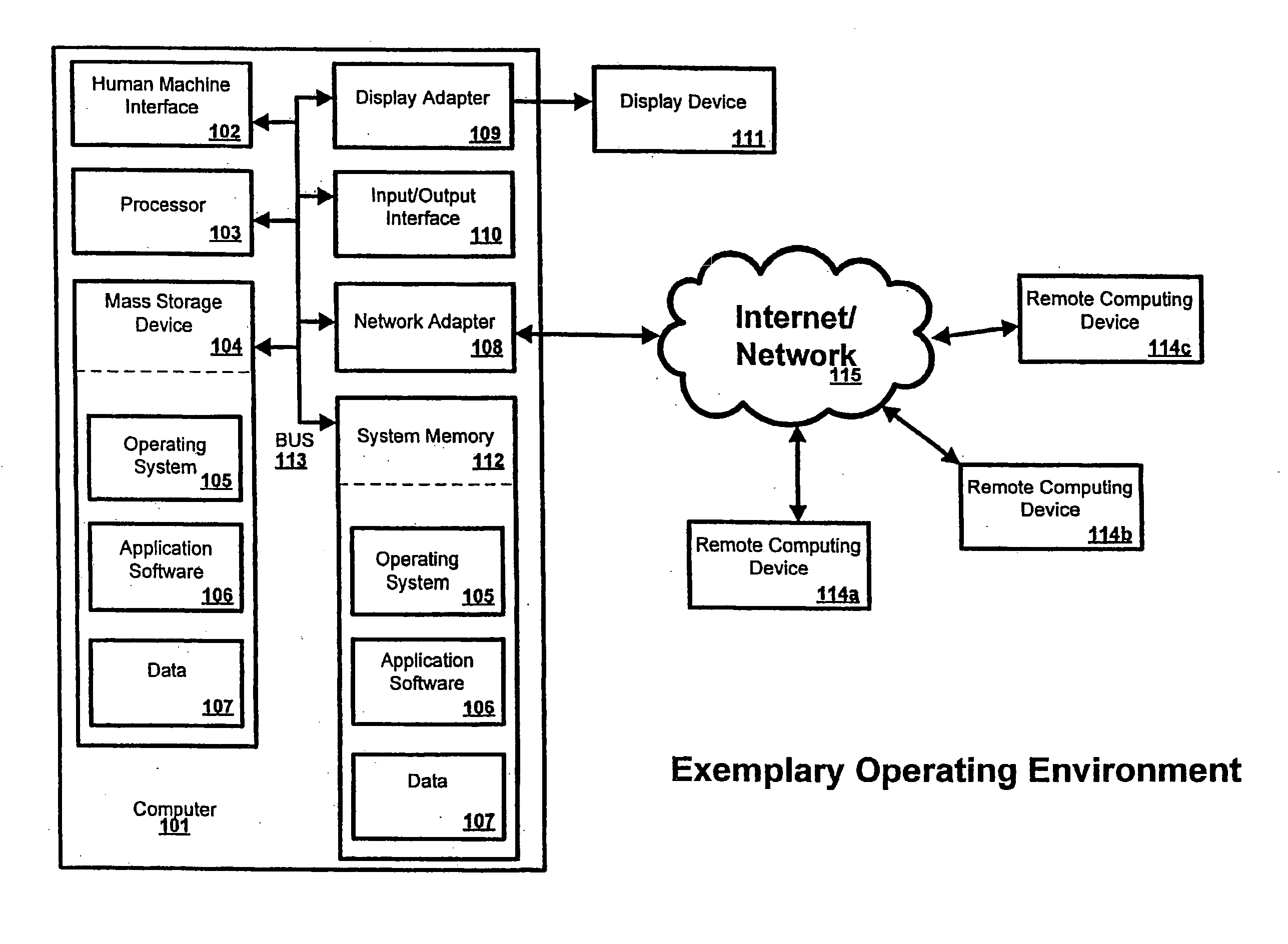
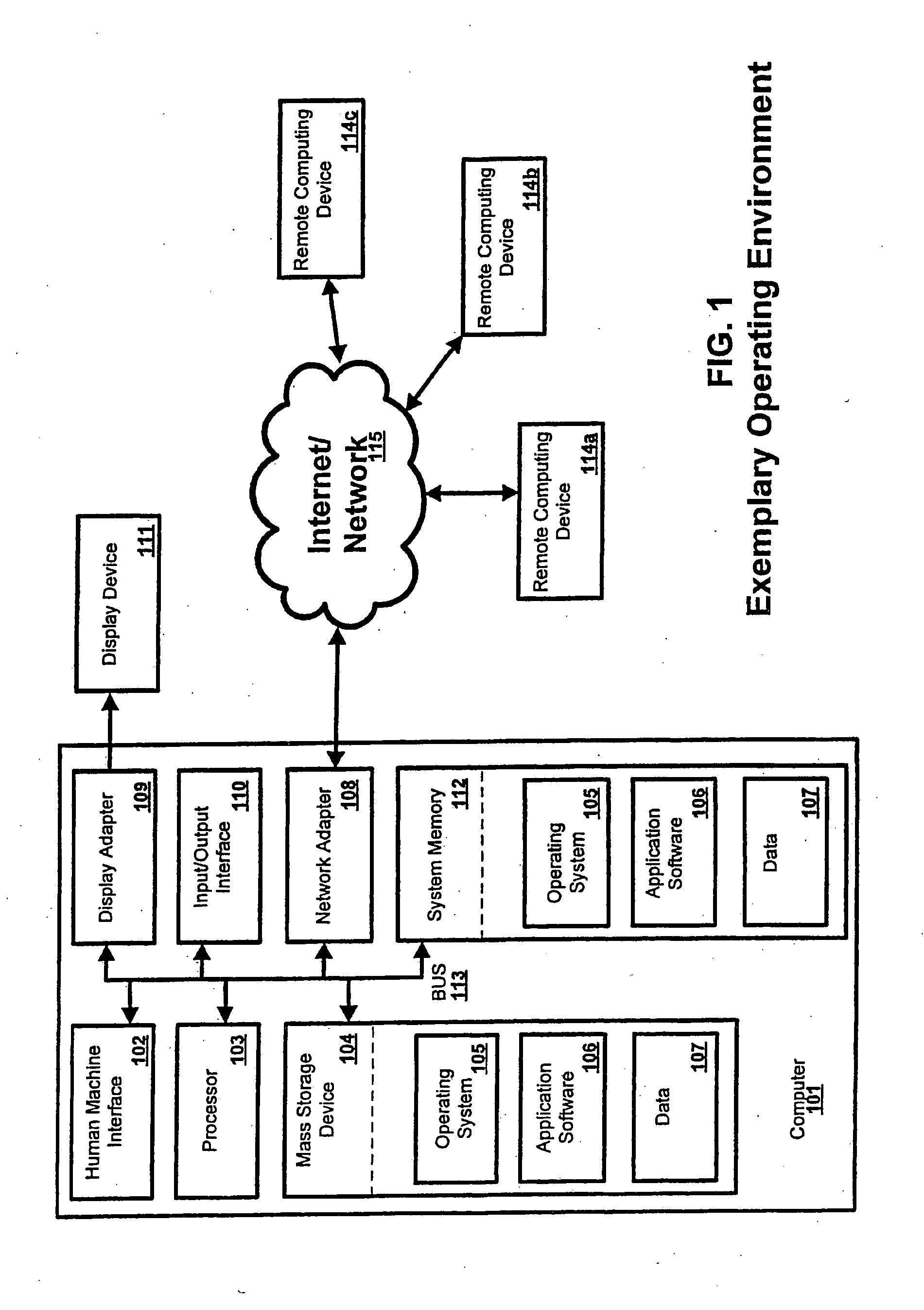
[0214]FIG. 23 is a block diagram showing exemplary system according to an embodiment of the present invention. The exemplary system 2300 is interfaced with a linear array 2302 having, for example, up to 256 elements. A bundle of micro coax cables 2304 provides transmission of the signals between the array 2302 and the processing unit 2306. The exemplary system funrther comprises a processing unit.

[0215] The processing unit 2306 is partitioned into two major subsystems. The first is the front end 2308, which includes the beamformer, the front end electronics, the beamformer controller and the signal processing module. The second is the computer unit 2310, or back end. The front end subsystem 2308, is concerned with transmit signal generation, receive signal acquisition, and signal processing. The back end 2310, which can be an off-the-shelf PC motherboard, is concerned with system control, signal and image processing, image display, data management, and the user interface. Data can ...

example 2

[0313] Another exemplary embodiment of the high frequency ultrasound imaging system comprises a modular, software-based architecture described below and as shown in FIG. 31.

[0314] The embodiment of FIG. 31 comprises four modules, which are part of a processing unit, for the exemplary system; a beamformer module 3102; an RF buffer memory 3104; a signal processing module 3106; and a system CPU 3108. The beamformer module 3102 comprises the circuitry for transmitting and receiving pulses from the transducer, as well as the delay processing used for beamforming. Its output can be summed RF data or optionally down-converted I and Q data from quadrature sampling techniques. The output of the beamformer module 3102 may be written to a large RF buffer memory 3104, as described herein.

[0315] The CPU / signal processing module 3106 is responsible for processing the RF data from the beamformer 3102 for image formation, or Doppler sensing. The signal processing module 3106 can comprise a CPU mo...

example 3

[0396] An embodiment of the exemplary system interface to an array with up to 256 elements may be used to obtain ultrasound images. Table 4 shows exemplary depth range, field of view, frame rate in B-Mode and frame rate in color flow imaging (CFI) for acquiring images. These operating parameters can be used for the particular small animal imaging application described in the far left column. As would be clear to one skilled in the art, however, other combinations of operating parameters can be used to image other anatomic structures or portions thereof, of both small animal and human subjects.

[0397] A small animal subject is used and the animal is anesthetized and placed on a heated small animal platform. ECG electrodes are positioned on the animal to record the ECG waveform. A temperature probe is positioned on the animal to record temperature. The important physiological parameters of the animal are thereby monitored during imaging. The anesthetic used may be a for example isoflo...


PUM


Abstract

A system for acquiring an ultrasound signal comprises a signal processing unit adapted for acquiring a received ultrasound signal from an ultrasound transducer having a plurality of elements. The system is adapted to receive ultrasound signals having a frequency of at least 20 megahertz (MHz) with a transducer having a field of view of at least 5.0 millimeters (mm) at a frame rate of at least 20 frames per second (fps). The signal processing can further produce an ultrasound image from the acquired ultrasound signal. The transducer can be a linear array transducer, a phased array transducer, a two-dimensional (2-D) array transducer, or a curved array transducer.

Description

CROSS REFERENCE TO RELATED APPLICATIONS [0001] This application claims the benefit of U.S. Provisional Patent Application No. 60 / 733,091 filed Nov. 2, 2005, and the benefit of U.S. Provisional Patent application No. 60 / 733,089 filed Nov. 2, 2005, both of which are fully incorporated herein and made a part hereof.BACKGROUND OF THE INVENTION [0002] Ultrasound echography systems using an arrayed transducer have been used in human clinical applications where the desired image resolution is in the order of millimeters. Operating frequencies in these clinical systems are typically below 10 MHz. With these low operating frequencies, however, such systems are not appropriate for imaging where higher resolutions are needed, for example in imaging small animals such as mice or small tissue structures in humans. [0003] Moreover, small animal imaging applications present several challenging requirements which are not met by currently available imaging systems. The heart rate of an adult mouse m...

Claims


Application Information

Patent Timeline
Patent Type & Authority Applications(United States)
IPC IPC(8): A61B8/00
CPCG01S7/52017A61B8/565G01S7/52088G01S7/52095G01S7/524G01S7/526G01S15/8927G01S15/8956G01S15/8959G01S15/8997G10K11/341G10K11/346G01S7/5202G01S15/8915A61B8/56G01S7/52034
Inventor MEHI, JAMESDAIGLE, RONALD E.BRASFIELD, LAURENCE C.STARKOSKI, BRIANWEN, JERROLDLIU, KAI WENPFLUGRATH, LAUREN S.FOSTER, F. STUARTHIRSON, DESMOND
Owner SUNNYBROOK HEALTH SCI CENT
Why Eureka
Try Eureka