Magnetic Resonance Imaging System and Magnetic Resonance Imaging Method

a magnetic resonance imaging and magnetic resonance imaging technology, applied in the field of magnetic resonance imaging system and magnetic resonance imaging method, can solve the problem of not fully achieving the improvement of the snr due to averaging

Inactive Publication Date: 2007-10-18
HITACHI MEDICAL CORP
View PDF6 Cites 10 Cited by
  • Summary
  • Abstract
  • Description
  • Claims
  • Application Information

AI Technical Summary

Benefits of technology

[0016] According to a magnetic response imaging system of the present invention, even when a resonant frequency varies along with a change

Problems solved by technology

This poses a problem in that the improvement of

Method used


Image

  • Magnetic Resonance Imaging System and Magnetic Resonance Imaging Method
  • Magnetic Resonance Imaging System and Magnetic Resonance Imaging Method
  • Magnetic Resonance Imaging System and Magnetic Resonance Imaging Method

Examples


first embodiment

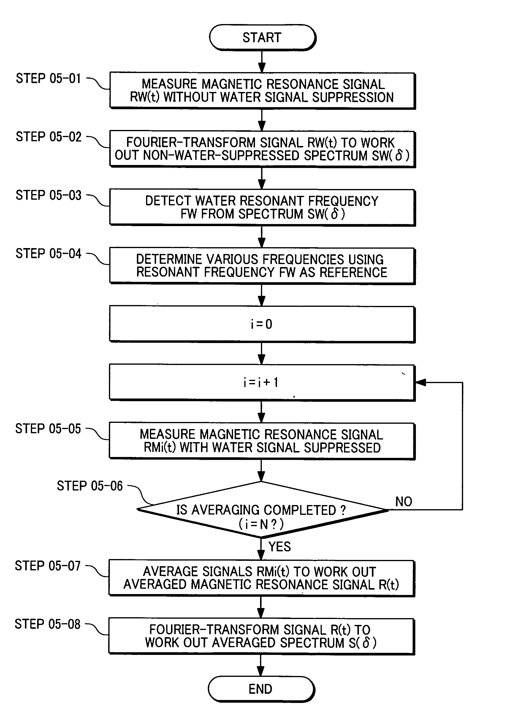
[0047]FIG. 6 shows an imaging procedure employed in the first embodiment of the present invention.

[0048] In the present embodiment, during water-suppressed spectrum measurement (main scan) accompanied by repetitive measurement intended for averaging of signals, non-water-suppressed spectrum measurement (pre-scan) is performed cyclically in order to cyclically detect a water resonant frequency (water-signal peak position) and a phase value at the water-signal peak from an obtained non-water-suppressed spectrum (the cyclic pre-scan makes it possible to sense the time-varying rate of the static magnetic field strength (resonant frequency)). During the water-suppressed spectrum measurement (main scan) succeeding the pre-scan, a reception-initiating phase value that is used for detection of a magnetic resonance signal is set to a value calculated from a phase value at the water-signal peak position detected during the pre-scan. For averaging of measured magnetic resonance signals, after...

second embodiment

[0062]FIG. 7 described an imaging procedure employed in the second embodiment of the present invention.

[0063] In the present embodiment, non-water-suppressed spectrum measurement (pre-scan) is cyclically performed during water-suppressed spectrum measurement (main scan) accompanied by repetitive measurement intended for averaging of signals. A phase change in an obtained non-water-suppressed time-sequential signal is detected and recorded. The cyclic pre-scan makes it possible to sense a time-varying rate of static magnetic field strength (resonant frequency). During the water-suppressed spectrum measurement (main scan) succeeding the pre-scan, phase correction is performed on a measured water-suppressed time-sequential signal in order to change the recorded phase changes in the non-water-suppressed time-sequential signals into a predetermined phase characteristic.

[0064] Step 07-01: the MRS sequence shown in FIG. 3 is used to acquire a magnetic resonance signal RWi(t) generated fr...


PUM


Abstract

Provided is a magnetic resonance imaging system capable of reducing degradation in a magnetic resonance spectrum derived from a change in a static magnetic field. A sequence controller performs non-water-suppressed spectrum measurement (pre-scan) cyclically during water-suppressed spectrum measurement (main scan) accompanied by repetitive measurement intended for averaging of signals, and cyclically detects a water resonant frequency (water-signal peak position) and a phase value at a water-signal peak from an obtained non-water-suppressed spectrum (the cyclic pre-scan makes it possible to sense a time-varying rate of static magnetic field strength (resonant frequency)). For the water-suppressed spectrum measurement (main scan) succeeding the pre-scan, a reception-initiating phase value that is used to detect a magnetic resonance signal is set to a value calculated using the phase value at the water-signal peak position detected during the pre-scan. For averaging of measured magnetic resonance signals, data items are shifted by the value calculated from the phase value at the water-signal peak position detected during the pre-scan. Thereafter, the averaging is carried out.

Description

TECHNICAL FIELD [0001] The present invention relates to a magnetic resonance imaging technology, or more particularly, to a magnetic resonance imaging system and a magnetic resonance imaging method which are preferable for measurement of a magnetic resonance signal that contains information on a chemical shift. BACKGROUND ART [0002] Magnetic resonance imaging systems excite nuclear magnetizations of respective protons contained in a subject, who is placed in a static magnetic field, by irradiating a radiofrequency magnetic field of a specific frequency to the subject (magnetic resonance phenomenon), detect a magnetic resonance signal generated from the subject, and thus acquire physical or chemical information. Magnetic resonance imaging (hereinafter abbreviated to MRI) that has widely prevailed provides an image which reflects a density distribution of a proton contained mainly in each of water molecules in the subject. In contrast to the MRI, a method of separating one magnetic re...

Claims


Application Information

Patent Timeline
IPC IPC(8): G01V3/14
CPCG01R33/56563
Inventor HIRATA, SATOSHIOCHI, HISAAKI
Owner HITACHI MEDICAL CORP
Why Eureka
Try Eureka