Oscillating circuit

a technology of oscillating circuit and ring, which is applied in the direction of pulse generation by logic circuit, pulse automatic control, pulse technique, etc., can solve the problems of ring vco not having structural symmetry with respect to power supply line and ground line, and not having excellent jitter and phase noise characteristics

Active Publication Date: 2007-10-18
SONY SEMICON SOLUTIONS CORP
View PDF3 Cites 17 Cited by
  • Summary
  • Abstract
  • Description
  • Claims
  • Application Information

AI Technical Summary

Benefits of technology

[0048] According to the present invention, it is possible to generate a plurality of oscillating signals having accurate phase differences using even numbers of inverters cascaded in the form of a ring.

Problems solved by technology

In addition, the ring VCO does not have structural symmetry with respect to a power supply line and a ground line, and does not have excellent jitter and phase noise characteristics.
Therefore the differential VCO is improved in terms of device noise and current consumption, but essentially has the same problems as described above.

Method used


Image

  • Oscillating circuit
  • Oscillating circuit
  • Oscillating circuit

Examples


first embodiment

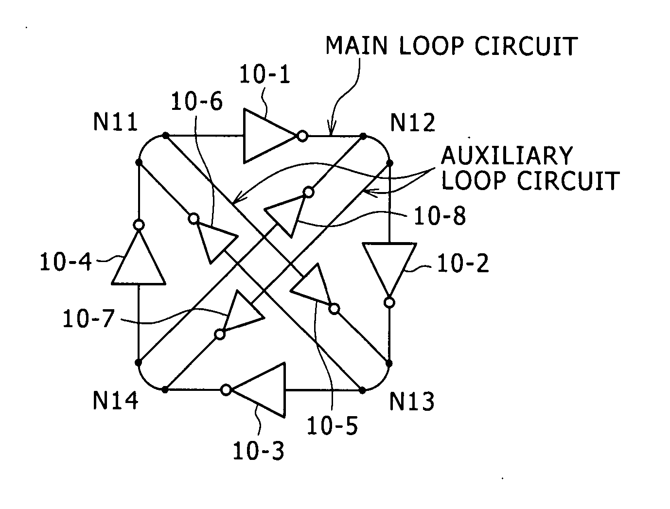
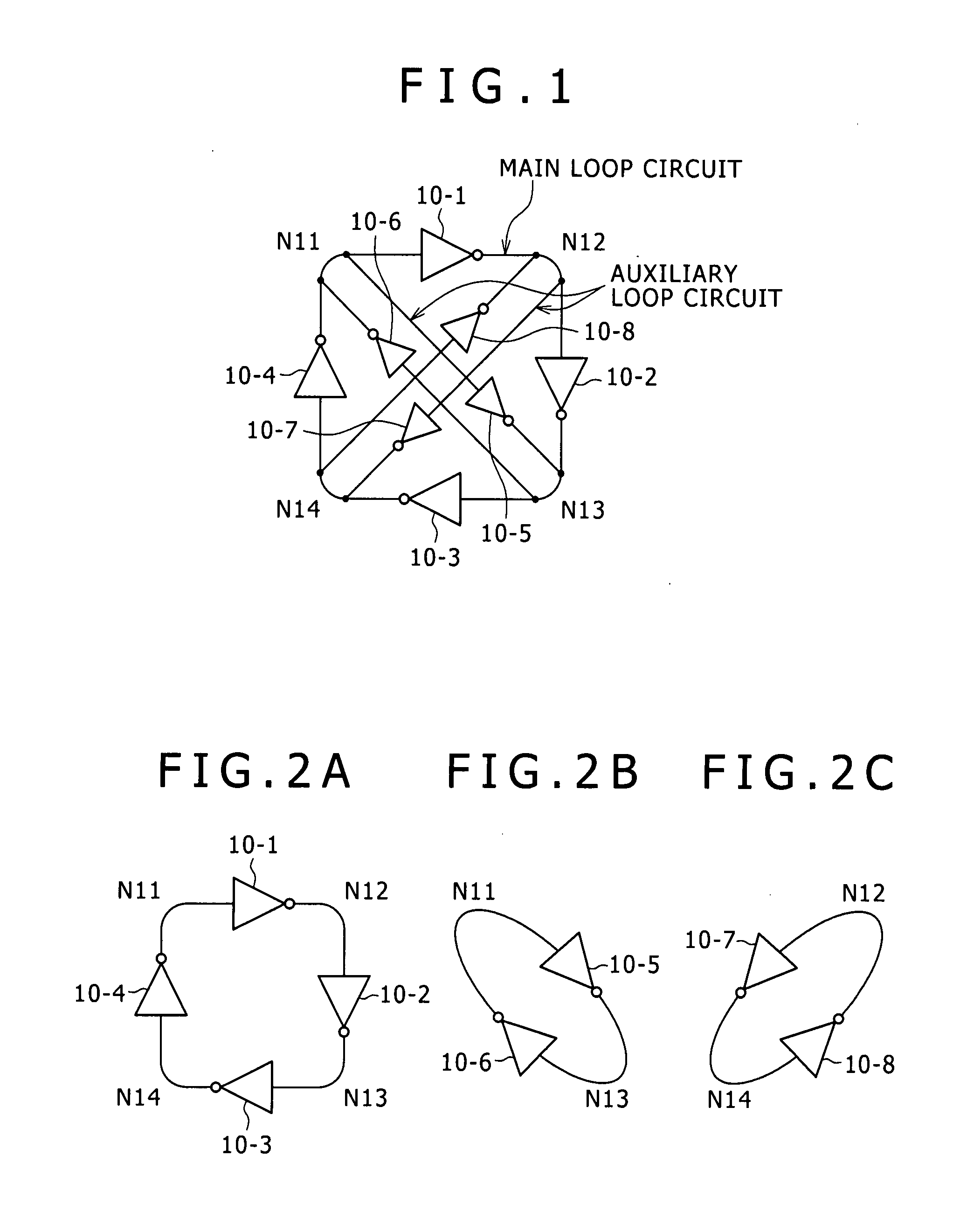
[0072] Constituent elements of an oscillating circuit according to an embodiment of the present invention will first be described with reference to FIGS. 1 to 4B.

[0073]FIG. 1 is a diagram showing an example of configuration of an oscillating circuit according to an embodiment of the present invention.

[0074]FIGS. 2A, 2B, and 2C are diagrams showing three loop circuits included in the oscillating circuit.

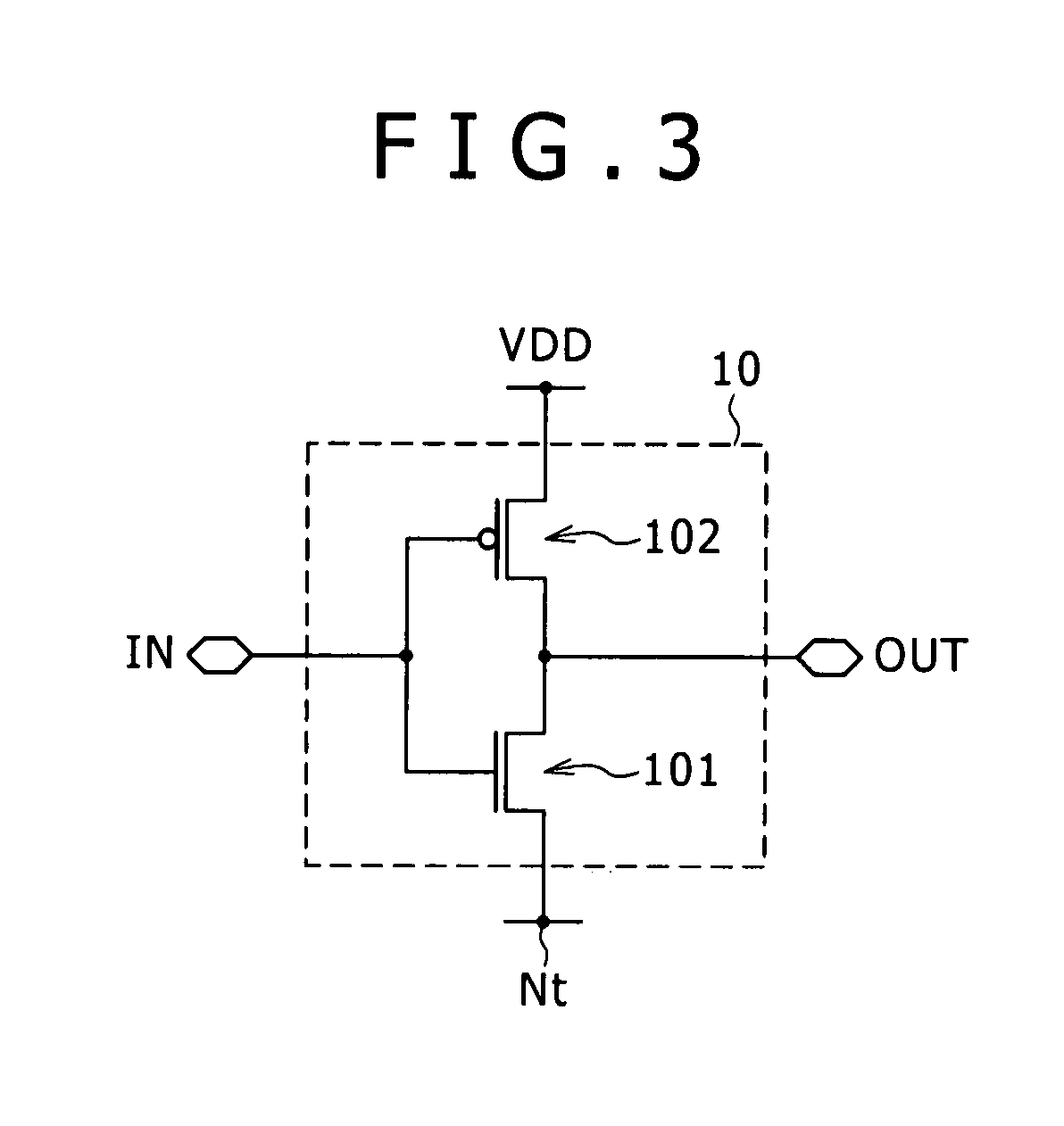
[0075]FIG. 3 is a diagram showing an example of an inverter (inverting circuit) forming the oscillating circuit.

[0076]FIGS. 4A and 4B are diagrams showing an example of a current source circuit for controlling the power supply current of each inverter.

[0077] The oscillating circuit shown in FIG. 1 has eight inverters (10-1 to 10-8). These inverters form three loop circuits as shown in FIGS. 2A to 2C. Specifically, the inverters 10-1 to 10-4 form a main loop circuit (FIG. 2A), the inverters 10-5 and 10-6 form an auxiliary loop circuit (FIG. 2B), and the inverters 10-7 and 10-8 for...


PUM


Abstract

An oscillating circuit includes N nodes outputting oscillating signals, a main loop circuit including N inverting circuits, and a plurality of auxiliary loop circuits. Each inverting circuit in the auxiliary loop circuits is connected in parallel with even numbers of inverting circuits cascaded in the main loop circuit. The circuits for feeding back signals from outputs to inputs of the respective inverters of the main loop circuit have circuit configurations equivalent to each other. Each inverting circuit in the main loop circuit and the auxiliary loop circuits drives an output line such that a phase of an output signal is inverted with respect to a phase of an input signal and has driving power that becomes lower when the phases of the output signal and the input signal are inverted with respect to each other than when the output signal and the input signal are in phase with each other.

Description

CROSS REFERENCES TO RELATED APPLICATIONS [0001] The present invention contains subject matter related to Japanese Patent Application JP 2006-098667 filed with the Japan Patent Office on Mar. 31, 2006, the entire contents of which being incorporated herein by reference. BACKGROUND OF THE INVENTION [0002] 1. Field of the Invention [0003] The present invention relates to an oscillating circuit that generates oscillating signals using inverting circuits cascaded in the form of a ring, and particularly to an oscillating circuit that can control oscillation frequency. [0004] 2. Description of the Related Art [0005] PLL (phase-locked loop) circuits are widely used to generate an oscillating signal with a high spectral accuracy or generate a clock signal locked in frequency and phase to a data signal. Examples of applications of the PLL circuit include radio communications of portable telephones and the like, serial communications through various cables, and reproducing systems (read channe...

Claims


Application Information

Patent Timeline
Patent Type & Authority Applications(United States)
IPC IPC(8): H03K3/03
CPCH03B27/00H03K3/0322H03K3/0315H03K3/03
Inventor UENO, YOSUKE
Owner SONY SEMICON SOLUTIONS CORP
Why Eureka
Try Eureka