Vertically polarized traveling wave antenna apparatus and method

a traveling wave antenna and vertical polarization technology, applied in the field ofradiating systems, can solve the problems of severe deformation of gain, limited power handling of traditional whip antennas for uhf, and limited flexibility of elevation radiation pattern, and achieve excellent azimuth pattern circularity and high power capability.

Inactive Publication Date: 2007-10-18
SPX CORP
View PDF5 Cites 32 Cited by
  • Summary
  • Abstract
  • Description
  • Claims
  • Application Information

AI Technical Summary

Benefits of technology

[0017]The foregoing needs are met, to a great extent, by the present invention, wherein in one aspect a vertically polarized traveling wave antenna is provided that in some embodiments permits simplicity in its mechanical construction, minimal design adaptation to vary beam tilt and null fill, matched input impedance substantially independent of the number of elements, excellent azimuth pattern circularity, and high power capability.

Problems solved by technology

Traditional whip antennas for UHF are limited in power handling, and are further limited in elevation radiation pattern flexibility.
The center feed arrangement shown in FIG. 1 inherently limits the amount of beam tilt that can be achieved, with no more than about 2 degrees of tilt possible before the elevation pattern develops a split beam and the gain is severely degraded.
One consideration in building long arrays of elements is that as array length increases, the connection of additional elements results in increased input impedance mismatch.
While very high power capability and precise beam control can be supported, high efficiency at moderate power may be uneconomical.

Method used


Image

  • Vertically polarized traveling wave antenna apparatus and method
  • Vertically polarized traveling wave antenna apparatus and method
  • Vertically polarized traveling wave antenna apparatus and method

Examples


Embodiment Construction

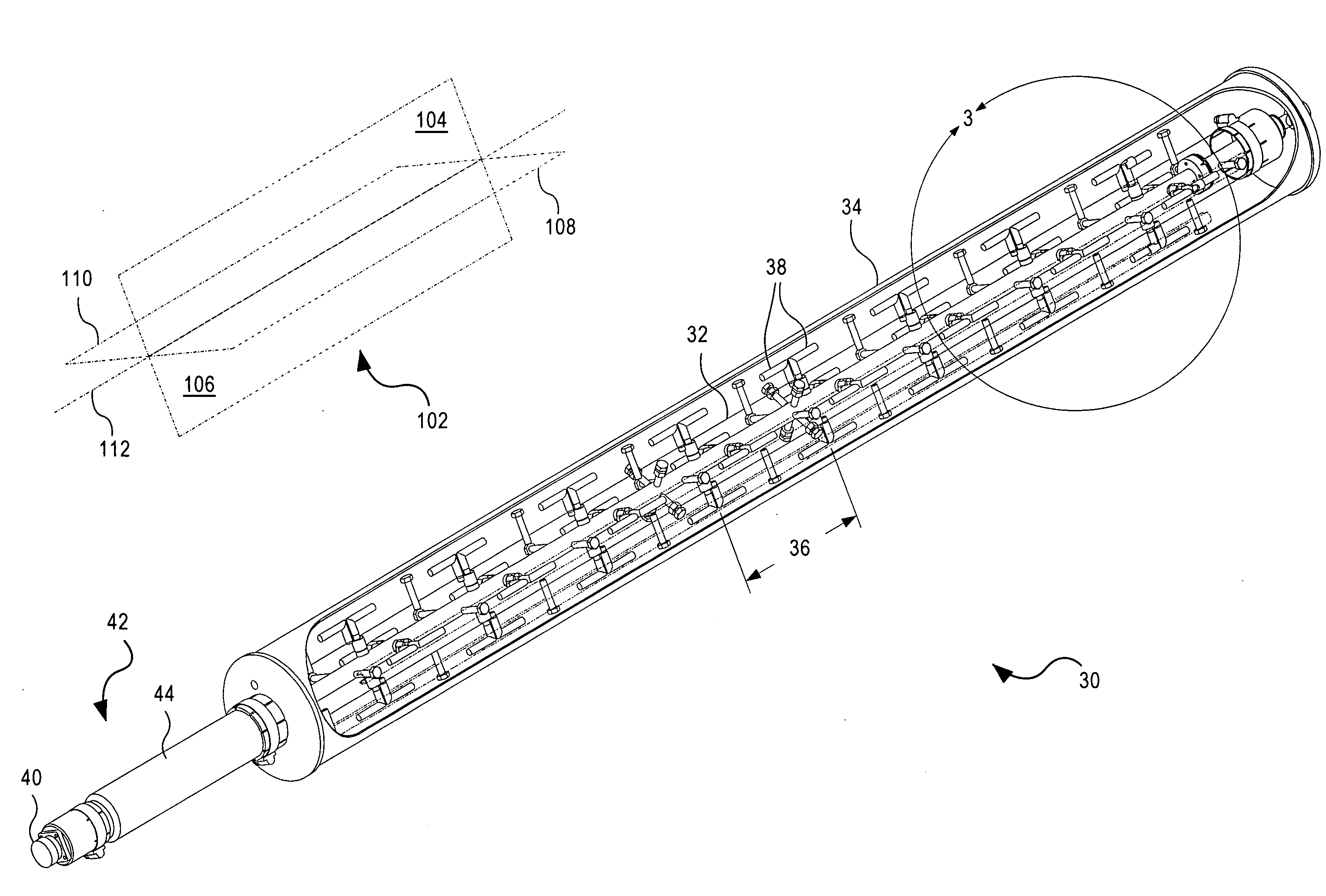
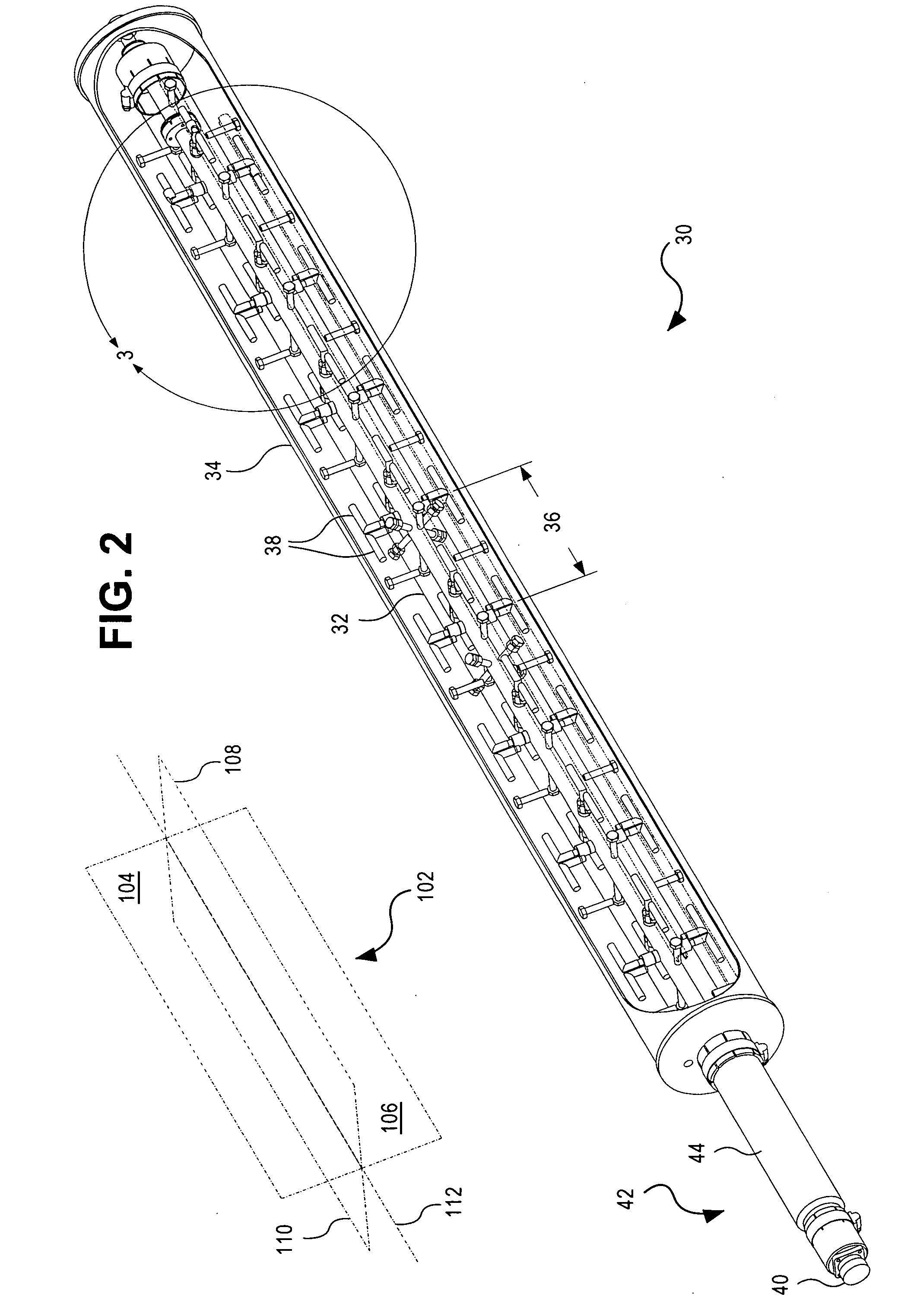
[0033]The invention will now be described with reference to the drawing figures, in which like reference numerals refer to like parts throughout. The present invention provides an apparatus and method that in some embodiments provides a vertically polarized traveling wave antenna.

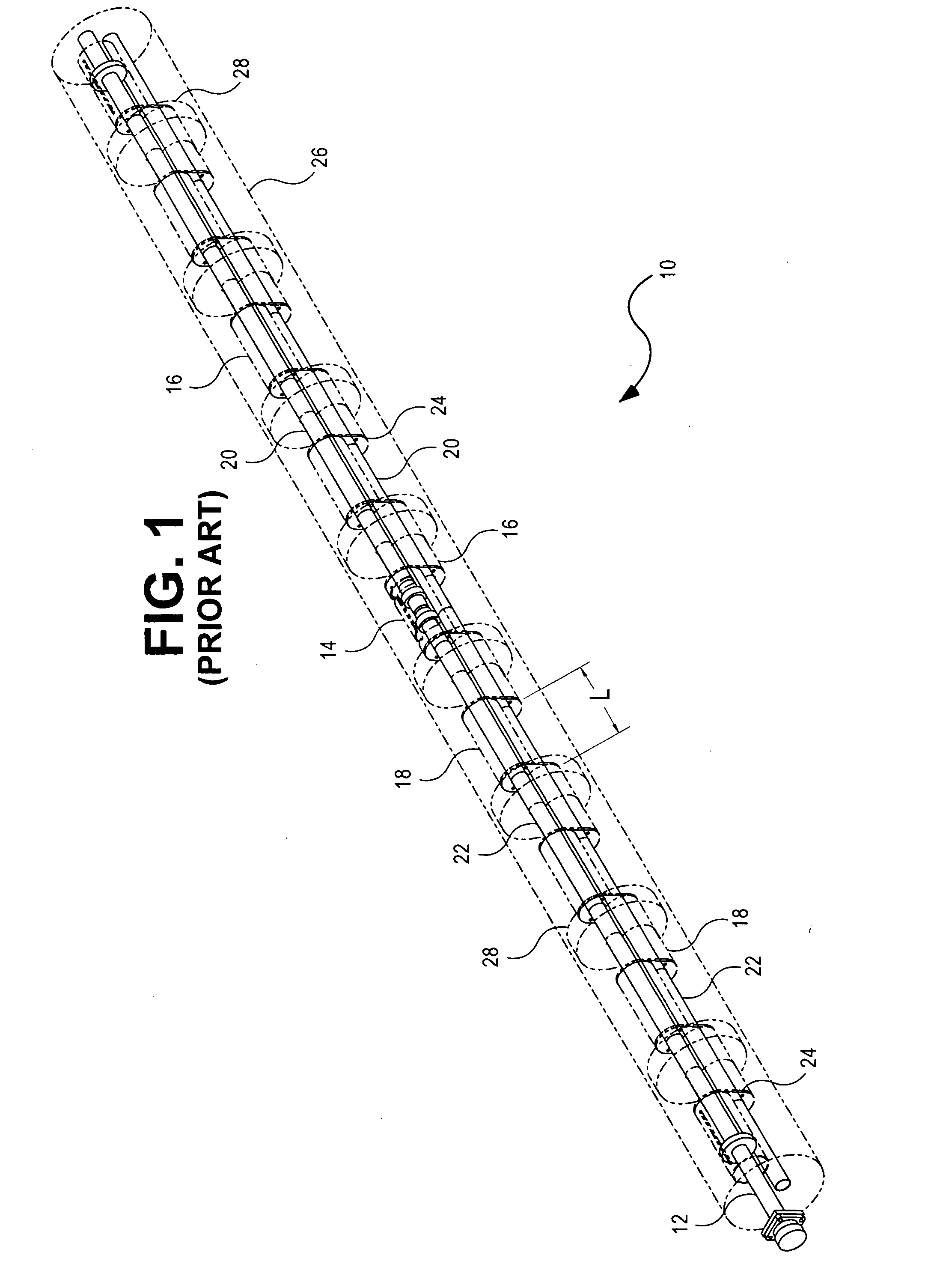
[0034]FIG. 1 is a perspective view of a “whip” antenna 10 used according to known practice for broadcast and transceiver functions in the upper L band and nearby frequency bands. The particular whip antenna embodiment shown is center fed using a coax 12 to a center divider 14. From the divider 14, interleaved and stacked coax segments 16, 18 function as omnidirectional radiators while propagating the signal up and down the whip 10. Each of these coax segments 16, 18 has a center conductor 20, 22 as large as the outer conductor of the feed coax 12; indeed, the lower coax 18 uses the outer surface of the outer conductor of the feed coax 12 as its center conductor 22. In order for the antenna 10 to function as...


PUM


Abstract

A vertically polarized traveling wave antenna is omnidirectional, bottom-mounted, and bottom-fed. A robust center coax provides a self-supporting mechanical structure. Multiple dipoles are capacitively coupled to the coax in quads, with a first two dipoles placed on opposite sides of the center coax and spaced by a quarter wavelength along the coax from the second two, which couple at right angles to the first two. This matched-layer spacing cancels the reactive components of the impedances of the dipoles. Beam tilt is readily incorporated over a wide range by adjusting layer spacing to add phase taper. All dipoles are oriented parallel to the coax axis, with opposite “hot” (center coupled) dipole elements oriented oppositely to each other. A radiated signal thus has rotating phase, when viewed from above, but is vertically polarized at each azimuth. A lightweight radome, provided for weather protection, is not needed for structural integrity.

Description

CLAIM OF PRIORITY[0001]This application claims priority to a U.S. nonprovisional application entitled, “Vertically Polarized Traveling Wave Antenna System and Method”, filed Apr. 14, 2006, having Ser. No. 60 / 791,887, which is hereby incorporated by reference in its entirety.FIELD OF THE INVENTION[0002]The present invention relates generally to radiating systems. More particularly, the present invention relates to traveling-wave linear array antennas.BACKGROUND OF THE INVENTION[0003]It is to be understood that the term “wavelength” as used herein in reference to the physical distance between successive equal-phase locations of a radio-frequency electromagnetic signal (the sense used throughout for the term of art “RF”), has a first definition in free space, wherein signals axiomatically propagate at the speed of light (C), a second definition in air, which is slightly shorter, and additional definitions on single conductors in free space and elsewhere, in transmission lines with air ...

Claims


Application Information

Patent Timeline
Patent Type & Authority Applications(United States)
IPC IPC(8): H01Q9/16
CPCH01Q1/246H01Q1/42H01Q21/10H01Q13/20H01Q9/28
Inventor SCHADLER, JOHN L.
Owner SPX CORP
Why Eureka
Try Eureka