
Power Capacitor

Inactive Publication Date: 2007-10-18
ABB TECH AG
View PDF10 Cites 12 Cited by
  • Summary
  • Abstract
  • Description
  • Claims
  • Application Information

AI Technical Summary

Benefits of technology

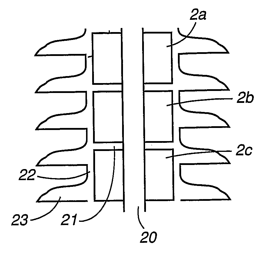
[0013] According to the first aspect of the invention, the above object has been achieved in that a power capacitor for high voltage of the kind described in the preamble to claim 1 comprises the special features that the container is substantially cylindrical and comprises, on its envelope surface, a plurality of creepage distance-extending protrusions of substantially a second polymer material and that the container is of a material which substantially comprises a first polymer material. The protrusions are shaped with regard to their thickness and radial length so that they also cool the capacitor.
[0014] Since the container is of a material that comprises a first polymer material, the need of insulation between the capacitor elements and the container is reduced. This also eliminates the risk of breakdown between the capacitor elements and the container. Further, the electrical connections of the capacitor may be made very simple and the necessary creepage distance between these may partly be obtained by the container itself. With the reduction of the need of insulation and because the electric bushings may be simplified, the capacitor will be relatively compact, thus offering a possibility of designing compact capacitor banks.
[0015] The choice of materials for the container causes the container to become resilient to a certain extent; it exhibits little sensitivity to cracking and combines good insulation property with other desired properties such as strength, handling ability, and cost.

Problems solved by technology

Such a capacitor bank thus comprises a plurality of different components and is relatively material-demanding.
Thus, extensive work is required for constructing such a capacitor bank.
Long lines for alternating voltage are inductive and consume reactive power.
The mechanical resonant frequency of the stack is amplified by specific frequencies of the current, which may result in a strong noise.
One disadvantage of a capacitor of a known type, for example of the kind described in the above-mentioned U.S. Pat. No. 5,475,272, is that the capacitor elements included therein must be insulated from the container.
Their external, flattened shape is unfavourable with respect to electric field reinforcement due to projecting foils, small radii, etc.
They must also be interconnected via internal patch cables in a manner that often creates further local irregularities in the electric field plot.
This leads to considerable requirements for electrical strength as far as the insulation against the container is concerned.
Damage to the container or insufficient sealing may lead to oil leaking out, which may damage the function of the capacitor and, in addition, contaminate the surroundings.
A further disadvantage of a conventional power capacitor is the sound generation that arises.

Method used


Image

  • Power Capacitor
  • Power Capacitor
  • Power Capacitor

Examples


Embodiment Construction

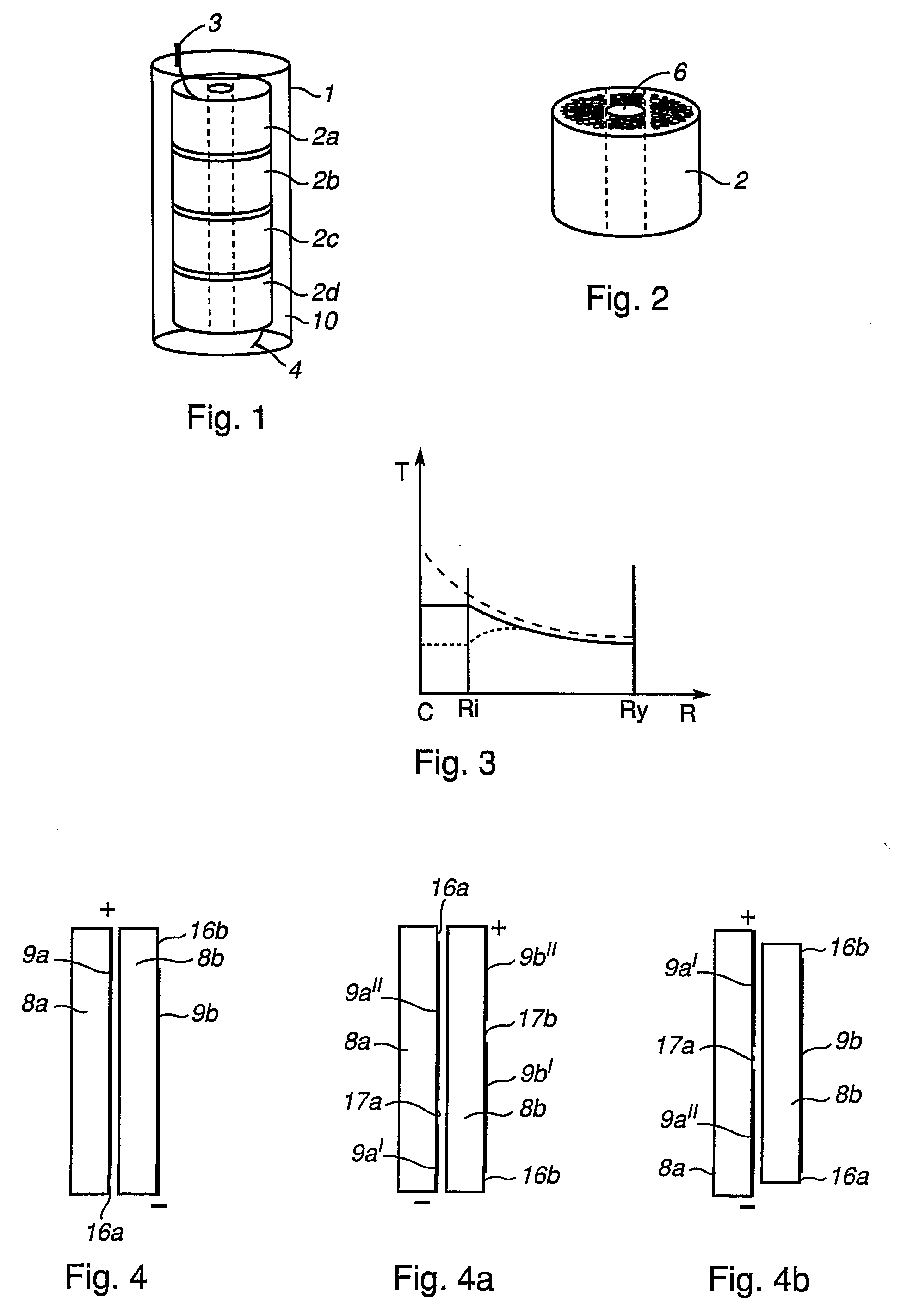
[0060]FIG. 1 shows the fundamental design of a capacitor according to the invention. It comprises an outer container 1 of polyethylene, in this case surrounding four capacitor elements 2a-2d. The container 1, as well as the capacitor elements 2a-2d, is circularly cylindrical. The capacitor elements 2a-2d are connected in series. At each end of the capacitor, a connection terminal 3, 4 is arranged. Each terminal consists of a conductive foil which is attached to the material of the container and extends therethrough. Between the capacitor elements 2a-2d and the container, a gel 10 is arranged. The gel serves as electrical insulation and as a thermal conductor.

[0061]FIG. 2 shows an individual capacitor element. This consists of metal-coated polymer films tightly rolled in a roll. The capacitor element 2 has a central axial through-hole 6 that may be used for cooling of the element. Typical dimensions of such a capacitor element is a diameter of 20-400 mm, preferably 150-250 mm, a bor...


PUM


Abstract

A power capacitor including at least one capacitor element enclosed in a container, wherein the container is of a material which substantially includes a first polymer material. Further, the container is cylindrical and provided in its surface with creepage distance extending protrusions of a second polymer material. The protrusions are formed with respect to their thickness and radial length so as to cool the capacitor. In a method for manufacturing such a power capacitor, a substantially cylindrical container is made of a material which substantially includes a first polymer material. The container is provided on its envelope surface with creepage distance-extending protrusions of a second polymer material and the capacitor elements are encapsulated in the container.

Description

TECHNICAL FIELD [0001] The present invention relates, from a first aspect, to a power capacitor of the kind that comprises at least one capacitor element enclosed in a container and surrounded by at least one insulating medium. From a second aspect, the invention also relates to a method for manufacturing such a capacitor. [0002] The power capacitor according to the invention is primarily intended for a rated voltage that exceeds 1 kV, for example 5 kV, preferably at least 10 kV. BACKGROUND ART [0003] Power capacitors are important components in systems for transmission and distribution of electric power for both alternating current and direct current. Power capacitor installations are mainly used for increasing the power-transmission capacity through parallel and series compensation, for voltage stabilization through static var systems and as filters for eliminating harmonics. [0004] Capacitors have a phase angle that is close to 90° and therefore generate reactive power. By connec...

Claims


Application Information

Patent Timeline
IPC IPC(8): H01G4/224H01B17/50H01B17/54H01C7/12H01GH01G4/30H01G4/38
CPCH01G4/224H01G2/08H01G4/385H01G4/38
Inventor DRUGGE, BIRGERMOOD, JOHANDOWLING, KENNETHLAIHONEN, SARIOLSSON, CARL-OLOFHOLMGREN, TOMMY
Owner ABB TECH AG
Learn More