Refrigerating Apparatus and Air Conditioner

a technology of refrigerating apparatus and air conditioner, which is applied in the direction of indirect heat exchangers, lighting and heating apparatus, heating types, etc., can solve the problems of increasing the number of parts and costs, the evaporation ability cannot be sufficiently controlled, and the opening of the heat source expansion valve cannot be reduced, so as to reduce the evaporation ability of the heat source heat exchanger, reduce the number of heat sources, and reduce the effect of evaporation ability

Inactive Publication Date: 2007-10-25
DAIKIN IND LTD
View PDF14 Cites 15 Cited by
  • Summary
  • Abstract
  • Description
  • Claims
  • Application Information

AI Technical Summary

Benefits of technology

[0051] Thus, in this air conditioner, even when control is conducted to reduce the evaporating ability of the heat source heat exchanger by reducing the opening of the heat source expansion valve in accordance with the air conditioning load of the plurality of utilization refrigerant circuits so that as a result the level of the refrigerant inside the heat source heat exchanger drops, the refrigerating machine oil does not accumulate inside the heat source heat exchanger. For this reason, the control width when the evaporating ability of the heat source heat exchanger is controlled with a heat source expansion valve can be expanded.
[0052] In this air conditioner, it becomes unnecessary to conduct control, as in conventional air conditioners disposed with plural heat source heat exchangers, to reduce the evaporating ability by closing some of the heat source expansion valves to reduce the number of heat source heat exchangers functioning as evaporators when the heat source heat exchangers are caused to function as evaporators or to reduce the evaporating ability by causing some of the heat source heat exchangers to function as condensers to offset the evaporating ability of the heat source heat exchangers functioning as evaporators. For this reason, a wide control width of the evaporating ability can be obtained by a single heat source heat exchanger.
[0053] Thus, because simplification of the heat source heat exchanger becomes possible in an air conditioner where simplification of the heat source heat exchangers could not be realized by restricting the control width of the control of the evaporating ability of the heat source heat exchangers, increases in the number of parts and cost that had occurred in conventional air conditioners as a result of disposing plural heat source heat exchangers can be prevented. Further, the problem of the COP becoming poor can be eliminated in an operating condition where, when some of the heat source heat exchangers are caused to function as condensers to reduce the evaporating ability, the amount of refrigerant compressed in the compression mechanism increases in correspondence to the amount of refrigerant condensed by the heat source heat exchangers and the air conditioning load of the entire plurality of utilization refrigerant circuits is small.

Problems solved by technology

However, even if one tries to reduce the amount of refrigerant flowing through the heat source heat exchangers by reducing the openings of the heat source expansion valves when the heat source heating exchangers are caused to function as evaporators with little evaporating ability, such as when the air conditioning load in the plural utilization refrigerant circuits becomes extremely small, the evaporating ability cannot be sufficiently controlled just by regulating the openings of the heat source expansion valves because the openings of the heat source expansion valves cannot be reduced that much due to the restriction of the level of the refrigerant inside the heat source heat exchangers.
For this reason, there are the problems that increases in the number of parts and cost arise as a result of disposing plural heat source heat exchangers, the amount of the refrigerant compressed in the compressor increases in correspondence to the amount of refrigerant condensed by the heat source heat exchangers when some of the plural heat source heat exchangers are caused to function as condensers to reduce the evaporating ability, and the COP becomes poor in an operating condition where the overall air conditioning load of the plural utilization refrigerant circuits is small.
Moreover, the gas fraction of the refrigerant after the high-pressure gas refrigerant has merged therewith from the pressurizing circuit becomes larger the more the openings of the heat source expansion valves are reduced, and drift arises between the plural utilization refrigerant circuits, resulting in the problem that the openings of the heat source expansion valves cannot be sufficiently reduced.
For this reason, there are the problems that increases in the number of parts and cost arise as a result of disposing plural heat source heat exchangers, the amount of the refrigerant compressed in the compressor increases in correspondence to the amount of refrigerant evaporated by the heat source heat exchangers when some of the plural heat source heat exchangers are caused to function as evaporators to reduce the condensing ability, and the COP becomes poor in an operating condition where the overall air conditioning load of the plural utilization refrigerant circuits is small.

Method used


Image

  • Refrigerating Apparatus and Air Conditioner
  • Refrigerating Apparatus and Air Conditioner
  • Refrigerating Apparatus and Air Conditioner

Examples


modification 1

(4) Modification 1

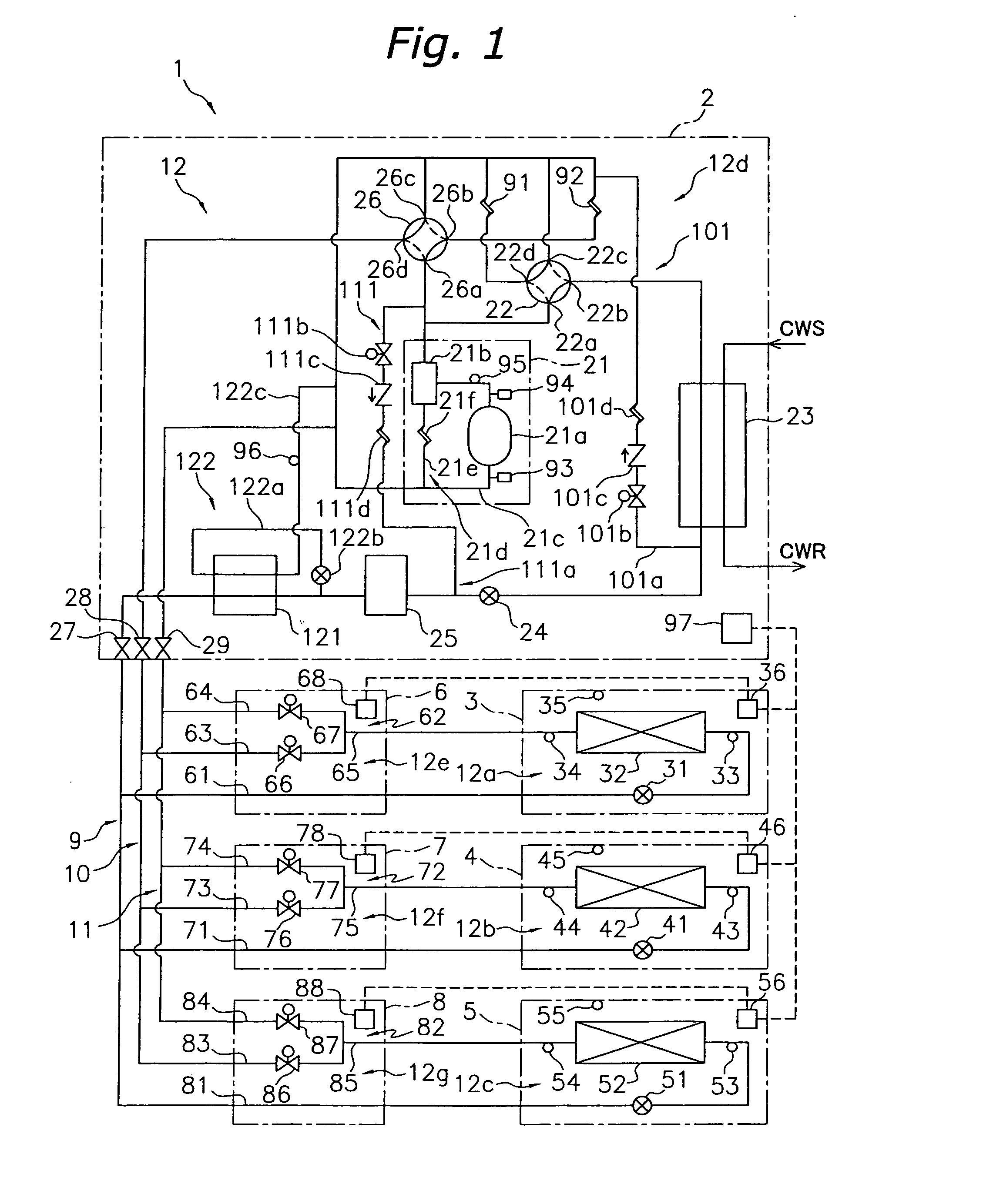
[0192] In the aforementioned air conditioner 1, the heat source unit 2 and the utilization units 3, 4 and 5 are connected via the refrigerant communication pipes 9, 10 and 11 and the connection units 6, 7 and 8 in order to configure an air conditioner capable of simultaneous cooling and heating. However, as shown in FIG. 8, the heat source unit 2 and the utilization units 3, 4 and 5 may also be connected via only the refrigerant communication pipes 9 and 10 in order to configure an air conditioner capable of simultaneous cooling and heating. Specifically, the air conditioner 1 of the present modification is configured such that the low-pressure gas refrigerant communication pipe 11 and the connection units 6, 7 and 8 necessary for making the air conditioner capable of simultaneous cooling and heating are omitted, the utilization units 3, 4 and 5 are directly connected to the liquid refrigerant communication pipe 9 and the high-pressure gas refrigerant communication...

modification 2

(5) Modification 2

[0206] In the aforementioned air conditioner 1, the first oil returning circuit 101, the pressurizing circuit 111, the cooler 121 and the cooling circuit 122 were disposed in the heat source unit 2 in order to expand both the control width of the control of the evaporating ability of the heat source heat exchanger 23 with the heat source expansion valve 24 and the control width of the control of the condensing ability of the heat source heat exchanger 23 with the heat source expansion valve 24. However, when the control width of the control of the condensing ability of the heat source heat exchanger 23 is ensured and it is necessary to expand only the control width of the control of the evaporating ability of the heat source heat exchanger 23, for example, just the first oil returning circuit 101 (i.e., omitting the pressurizing circuit 111, the cooler 121 and the cooling circuit 122) may be disposed in the heat source unit 2 as shown in FIG. 11 (i.e., the pressuri...

modification 3

(6) Modification 3

[0207] In the aforementioned air conditioner 1, four-way switch valves were used as the first switch mechanism 22 and the second switch mechanism 26, but the switch mechanisms are not limited thereto. For example, as shown in FIG. 12, three-way switch valves may also be used as the first switch mechanism 22 and the second switch mechanism 26.


PUM


Abstract

An air conditioner has a refrigerant circuit and a first oil returning circuit. The refrigerant circuit has a plurality of utilization refrigerant circuits each having a utilization heat exchanger and a utilization expansion valve connected to a heat source refrigerant circuit that includes a compression mechanism, a heat source expansion valve and a heat source heat exchanger configured so that a refrigerant flows in from below and flows out from above when the heat source heat exchanger functions as an evaporator. The heat source refrigerant circuit uses a combination of a refrigerating machine oil and a refrigerant that does not separate into two layers in a temperature range of 30° C. or below. The first oil returning circuit is connected to a lower portion of the heat source heat exchanger and returns the refrigerating machine oil accumulated inside the heat source heat exchanger to the compression mechanism together with the refrigerant.

Description

TECHNICAL FIELD [0001] The present invention relates to a refrigerating apparatus and an air conditioner, and particularly relates to a refrigerating apparatus and an air conditioner provided with a refrigerant circuit that has an evaporator configured so that refrigerant flows in from below and flows out from above. BACKGROUND ART [0002] Conventionally, there has been a refrigerating apparatus disposed with a vapor compression-type refrigerant circuit including a heat exchanger configured such that refrigerant flows in from below and flows out from above as an evaporator of the refrigerant (e.g., see Patent Document 1). In order to prevent refrigerating machine oil from accumulating inside the evaporator, the refrigerating apparatus is configured to extract, from the vicinity of the surface of the refrigerant, the refrigerating machine oil accumulating in a state where it floats on the surface of the refrigerant as a result of the refrigerating machine oil and the refrigerant separ...

Claims


Application Information

Patent Timeline
Patent Type & Authority Applications(United States)
IPC IPC(8): F25B1/00
CPCF25B31/004F25B39/02F25B2341/0016F24F3/06F28D9/00
Inventor HONDA, MASAHIRO
Owner DAIKIN IND LTD
Why Eureka
Try Eureka