Multi-die inductor

a multi-die, inductor technology, applied in transformer/inductance details, basic electric elements, solid-state devices, etc., can solve the problems of inductors inside the pll, inductors susceptible to electromagnetic interference, and inability to achieve such a high-q with conventional on-chip inductors, etc., to increase the cross-sectional area of the inductor and improve the quality factor of the inductor

Inactive Publication Date: 2007-10-25
SILICON LAB INC
View PDF30 Cites 31 Cited by
  • Summary
  • Abstract
  • Description
  • Claims
  • Application Information

AI Technical Summary

Benefits of technology

[0007]A technique for improving the quality factor of an inductor includes increasing a cross-sectional area of the inductor by increasing a vertical dimension associated with the inductor. In at least one embodiment of the invention, an apparatus includes an inductor formed partially in a first integrated circuit die and formed partially in at least a second integrated circuit die. The inductor may be formed partially in at least one inter

Problems solved by technology

It is difficult to achieve such a high-Q with conventional on-chip inductors using conductor and dielectric layer compositions and thicknesses which are typically encountered in traditional integrated circuit processes.

Method used


Image

  • Multi-die inductor
  • Multi-die inductor
  • Multi-die inductor

Examples


Embodiment Construction

)

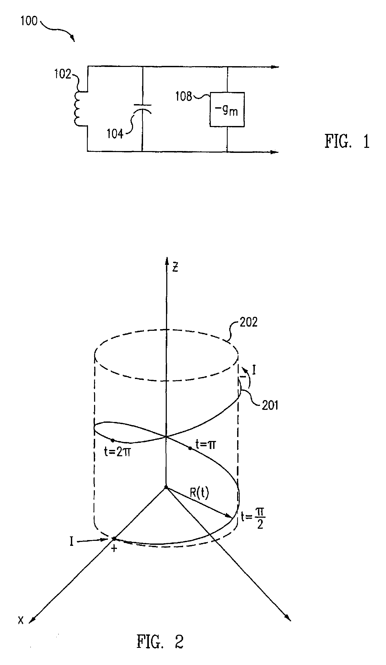
[0042]Referring to FIG. 1, an integrated circuit die includes an LC oscillator circuit e.g., circuit 100, including inductor 102, capacitor 104, and gain stage 108. The quality factor associated with the resonant circuit (i.e., QRESONANT) describes the ability of the circuit to produce a large output at a resonant frequency and also describes the selectivity of the circuit. The QRESONANT may be substantially affected by the quality factor of an inductor (i.e., QL) included in the resonant circuit. In general, QL for an inductor modeled as an inductance in series with a resistance is

QL=ωLR

where ω is the angular frequency of oscillation, L is the inductance of the inductor, and R is the effective series resistance of the inductor.

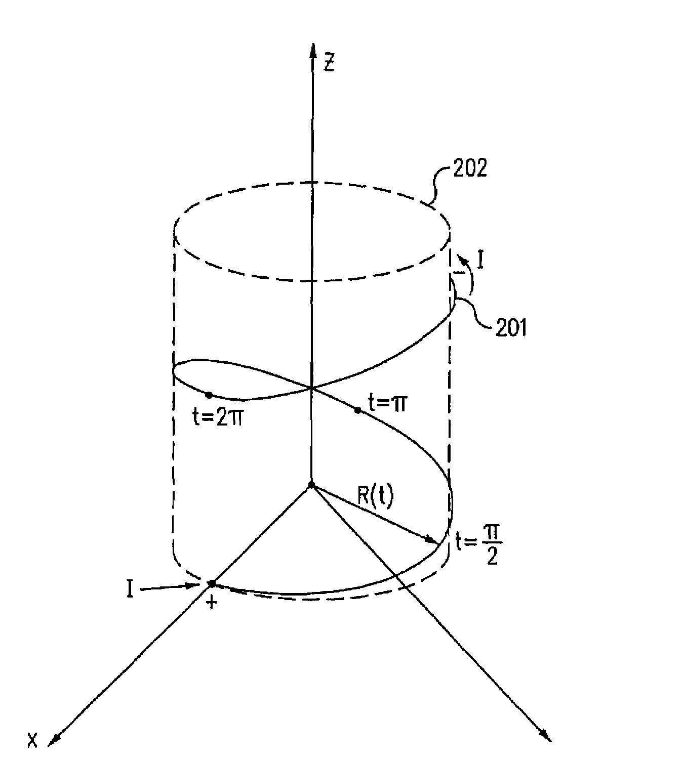
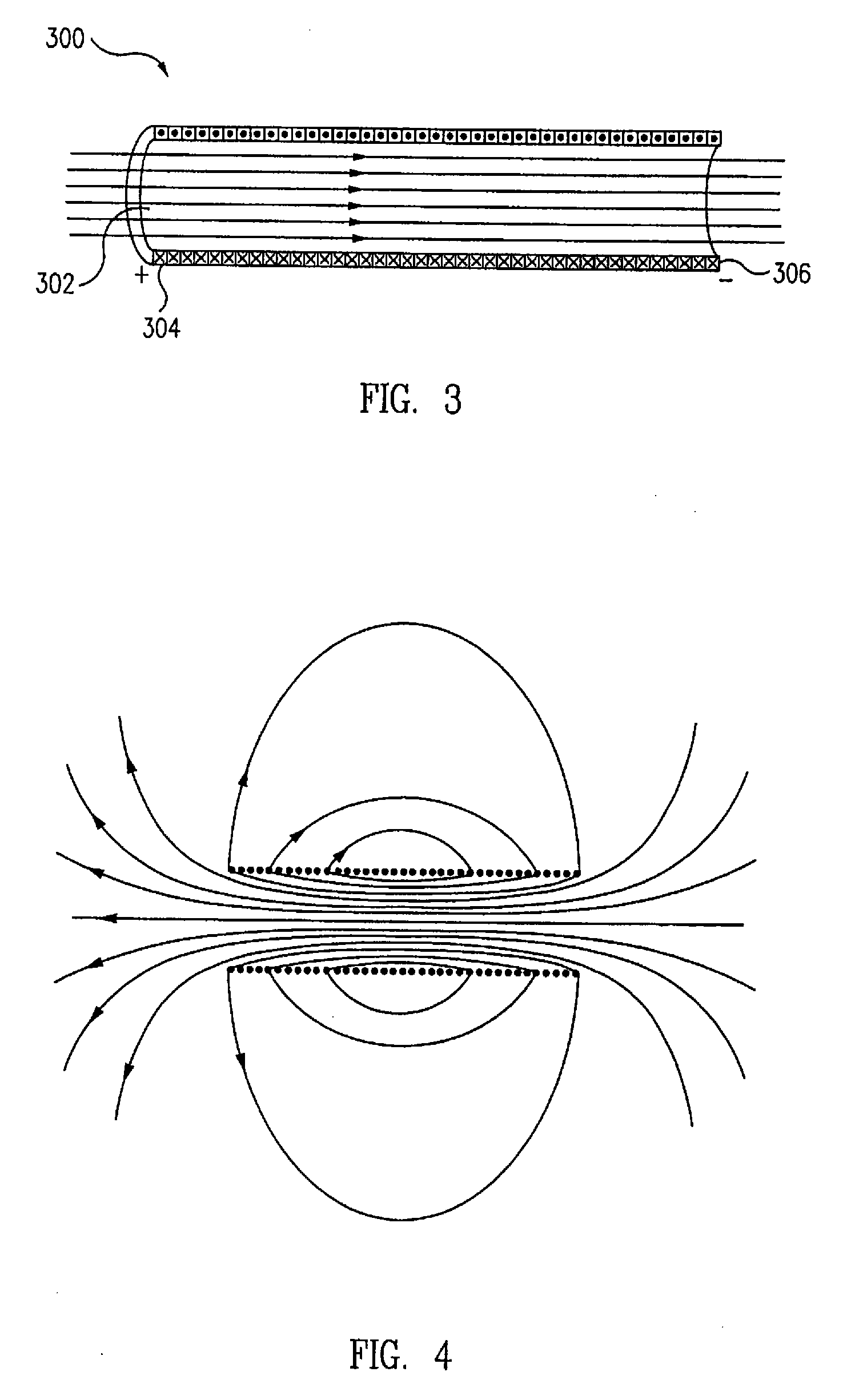
[0043]In general, an inductor includes an input, an output, and a coil disposed therebetween through which current rotates. The coil introduces inductance into an electrical circuit, to produce magnetic flux. As referred to herein, a coil is a conductor havi...


PUM


Abstract

A technique for improving the quality factor of an inductor includes increasing a cross-sectional area of the inductor by increasing a vertical dimension associated with the inductor. An apparatus includes an inductor formed partially in a first integrated circuit die and formed partially in at least a second integrated circuit die. The inductor may be formed partially in at least one interconnect structure between the first integrated circuit die and the second integrated circuit die. In at least one embodiment of the invention, the inductor is self-shielding and is configured to generate a magnetic field in response to a current flowing through coupled conductor portions of the self-shielding inductor. The magnetic field of the self-shielding inductor is substantially confined to a core region of the self-shielding inductor.

Description

CROSS-REFERENCE TO RELATED APPLICATION(S)[0001]This application claims the benefit under 35 U.S.C. §119(e) of U.S. Provisional Application No. 60 / 745,585, filed Apr. 25, 2006, entitled “MULTI-DIE INDUCTOR” by Ligang Zhang and John M. Czarnowski, which application is hereby incorporated by reference.BACKGROUND[0002]1. Field of the Invention[0003]The present invention relates to integrated circuits, and more particularly to such integrated circuits incorporating inductor structures.[0004]2. Description of the Related Art[0005]Many modern integrated circuit devices, e.g., stable oscillators, require a high-Q (i.e., quality factor) inductor that is immune to external noise sources to achieve desired specifications. Crystal oscillators may be employed, but typically require an off-chip crystal mounted elsewhere on a printed-wiring-board. LC oscillators offer the potential advantage of being able to incorporate such an oscillator on-chip.[0006]To achieve a suitable oscillator for certain ...

Claims


Application Information

Patent Timeline
IPC IPC(8): H01L23/552
CPCH01F27/367H01L2224/11334H01F2017/008H01L23/5227H01L23/642H01L23/645H01L24/73H01L25/0657H01L25/16H01L2221/68377H01L2224/16145H01L2224/32014H01L2224/32145H01L2224/48091H01L2224/48227H01L2225/0651H01L2225/06527H01L2225/06572H01L2924/01013H01L2924/01029H01L2924/01073H01L2924/01079H01L2924/01082H01L2924/09701H01L2924/15192H01L2924/15311H01L2924/1532H01L2924/19011H01L2924/19041H01L2924/19103H01L2924/30107H01L2924/3025H01F2017/004H01L2924/10329H01L24/48H01L2924/01005H01L2924/01006H01L2924/01019H01L2924/01033H01L2924/01047H01L2924/01087H01L2924/00014H01L2924/14H01L2224/73257H01F27/36H01F27/363H01L2924/00H01L2224/45099H01L2224/45015H01L2924/207
Inventor ZHANG, LIGANGCZARNOWSKI, JOHN M.
Owner SILICON LAB INC
Why Eureka
Try Eureka