X-Ray Target and Apparatuses Using the Same

a target and x-ray technology, applied in the field of x-ray targets, can solve the problems of unsatisfactory, unsuitable arrangement for x-ray radiographic or transmission imaging, and the x-ray radiography has remained in several m, and achieves the effect of high convenien

Inactive Publication Date: 2007-10-25
JAPAN SCI & TECH CORP
View PDF4 Cites 58 Cited by
  • Summary
  • Abstract
  • Description
  • Claims
  • Application Information

AI Technical Summary

Benefits of technology

[0027] Said transmission X-ray image preferably includes a contrast by phase contrast. This feature makes it possible to provide an X-ray microscope whereby there can be observed not only an absorption image of an observable object but also its phase contrast. Said X-ray detecting means is preferably an image sensor and provided with an image processing means for said image sensor. This feature makes it possible to provide the X-ray microscope that can process a variety of images and is therefore highly convenient.

Problems solved by technology

As the X-ray source that can be obtained by this method has a size of several μm generally, the resolution obtainable by the X-ray radiography has remained in several μm, too, which has not been satisfactory.
For this reason, different focus sizes are apt to be produced from different fine glass tubes, and the arrangement is unsuitable for X-ray radiographic or transmission imaging.
Further, there are also limits in machining such a fine glass tube.
However, while reducing the focus size of a conventional X-ray source as shown in FIG. 12 requires reducing the spot size of an electron beam and increasing the density of electrons in the electron beam for irradiation, the problem arises that if this is done, electrons forming the beam still then diffuse within the X-ray target and fail to give rise to a fine focus X-ray source.
Also, if the density of electrons is raised in the beam for irradiation, the problem emerges that this will cause the X-ray target material to be heated to a molten state and then to a sublimed or evaporated state, and will damage the target thin film 101.

Method used


Image

  • X-Ray Target and Apparatuses Using the Same
  • X-Ray Target and Apparatuses Using the Same
  • X-Ray Target and Apparatuses Using the Same

Examples


Embodiment Construction

[0041] The present invention will better be understood from the following detailed description and the drawings attached hereto showing certain illustrative forms of implementation of the present invention. In this connection, it should be noted that such forms of implementation illustrated in the accompanying drawings hereof are intended in no way to limit the present invention but to facilitate an explanation and understanding thereof. In the Figures, the same reference numerals are used to designate the same or corresponding parts.

First Form of Implementation

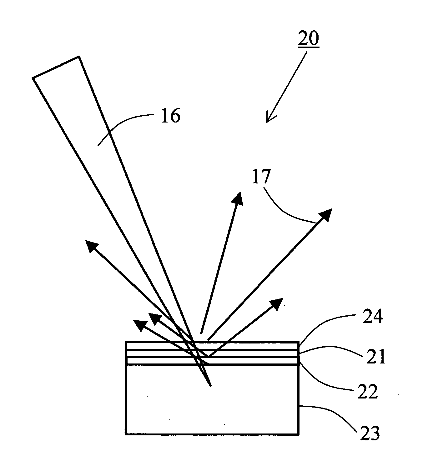
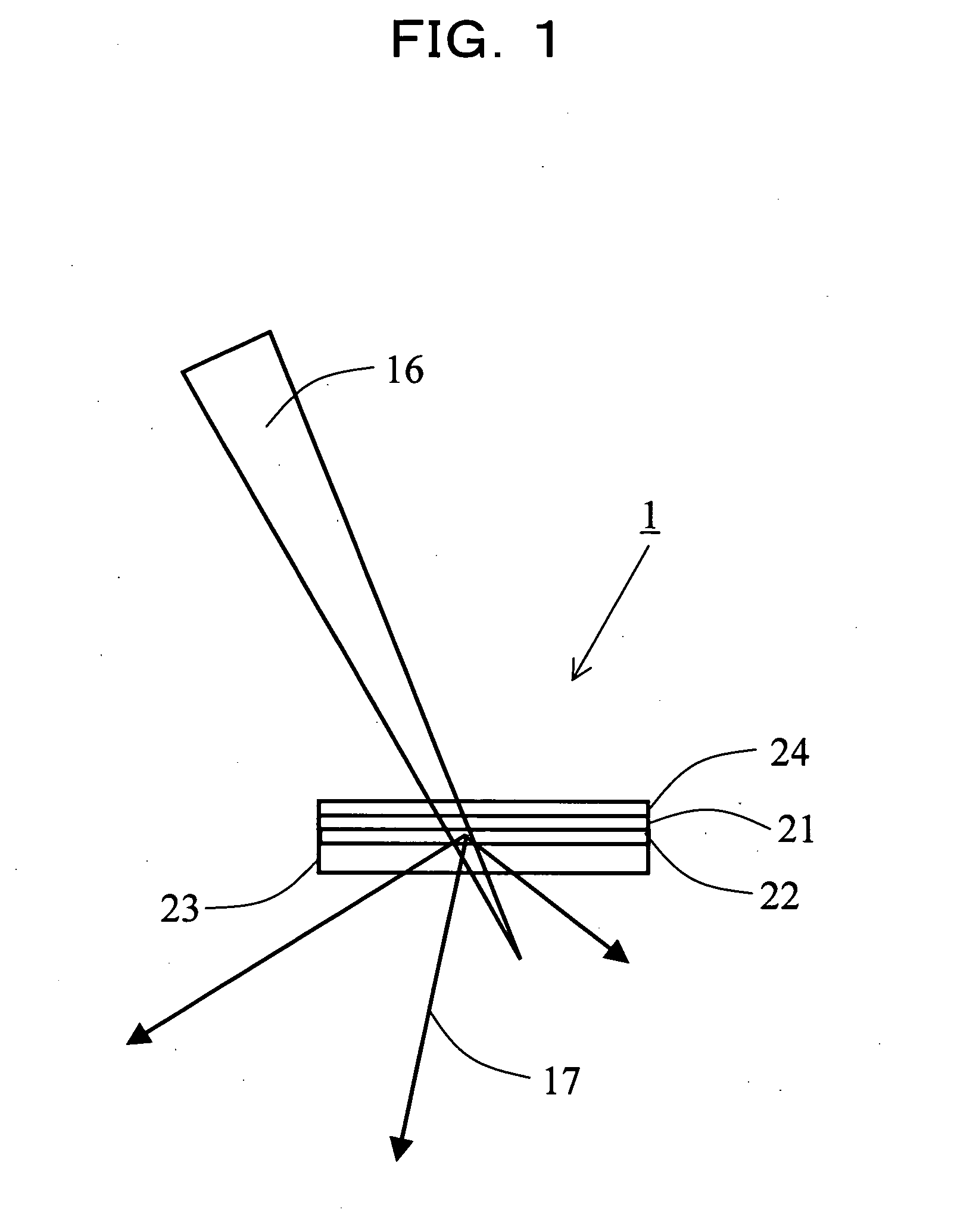
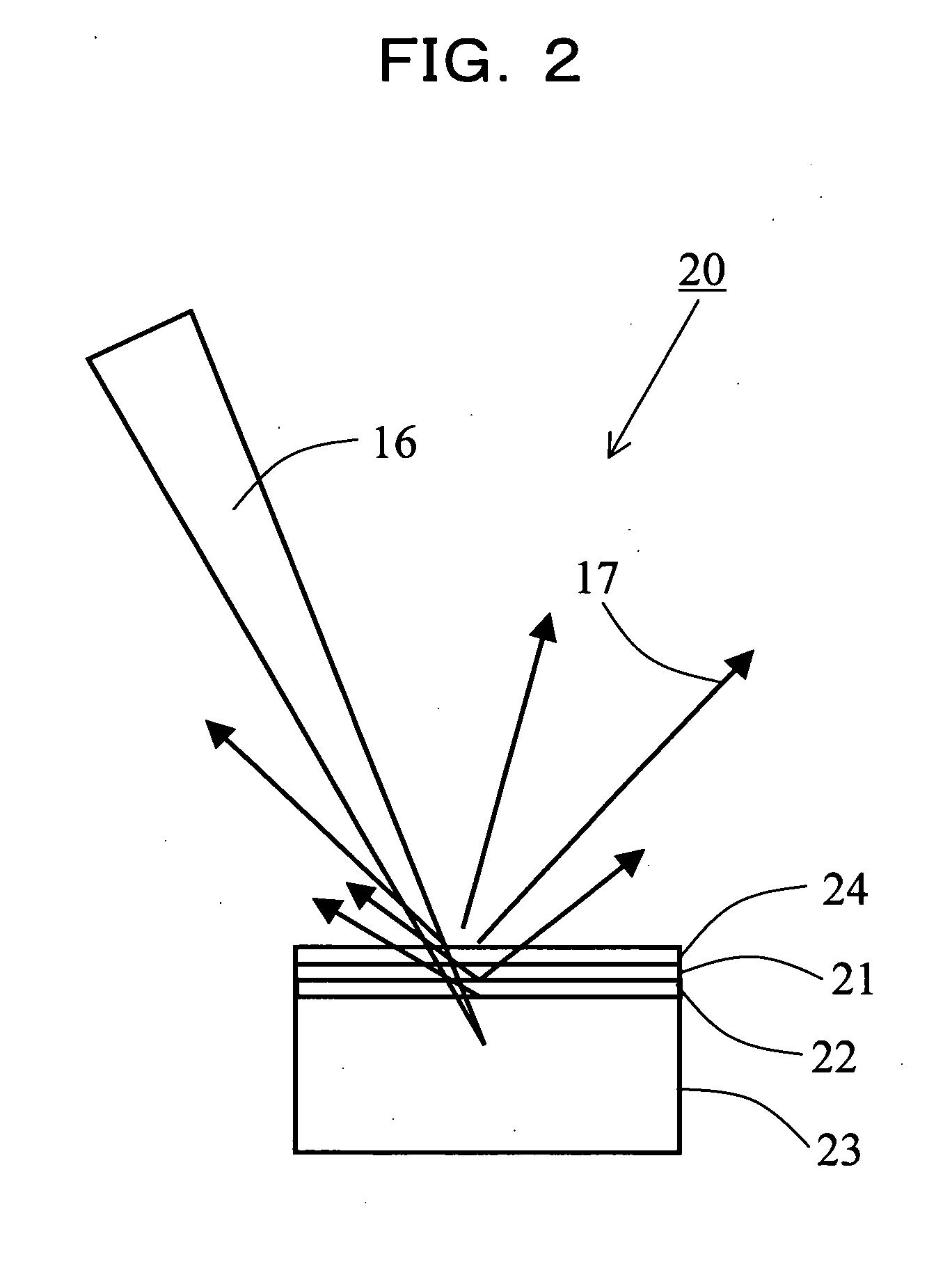
[0042]FIG. 1 is a cross sectional diagram illustrating the structure of an X-ray target according to a first form of implementation of the present invention. As shown in the FIG. 1, the X-ray target designated by reference numeral 1 comprises, from the above from which a convergent electron beam 16 is applied, a first cap layer 21, a target layer 22 on which the convergent electron beam 16 is focused to generate X-rays, an...


PUM

PropertyMeasurementUnit
diameteraaaaaaaaaa
thicknessaaaaaaaaaa
diameteraaaaaaaaaa

Abstract

Disclosed are an X-ray target having a micro focus size and capable of producing X-rays of high intensity, and apparatuses using such an X-ray target. The X-ray target (1) has a structure in which a first cap layer (21), a target layer (22), and a second cap layer (23) are successively laminated, wherein the first and second cap layers (21and 23) are each composed of a material which is lower in electron beam absorptivity than that of which the target layer (22) is composed. An X-ray generator using the X-ray target (1) can generate highly intense and nanofocus (several nm) X-rays (17). Using the X-ray generator, an X-ray microscope allows obtaining a high resolution transmission image, an X-ray diffraction apparatus allows obtaining an X-ray diffraction image of a very small area, and a fluorescent X-ray analysis apparatus allows making the fluorescent X-ray analysis of a minute area.

Description

TECHNICAL FIELD [0001] The present invention relates to an X-ray target having a nanofocus size and capable of producing X-rays of high intensity, and apparatuses using such an X-ray target. BACKGROUND ART [0002] X-rays can be used to make a detailed nondestructive examination of the internal structure of a material. For example, observation by transmission X-ray imaging has extensively been applied to such as the diagnosis of a living body in medical and pharmaceutical fields, the evaluation of various industrial products and an apparatus for the inspection of pieces of luggage in an airport. Other than those utilizing synchrotron radiation, the X-ray sources currently used include an X-ray tube based on the method of striking accelerated electrons on a metallic target in vacuum to emit X-rays from the target. As the X-ray source that can be obtained by this method has a size of several μm generally, the resolution obtainable by the X-ray radiography has remained in several μm, too...

Claims


Application Information

Patent Timeline
Patent Type & Authority Applications(United States)
IPC IPC(8): H01J35/08G01N23/04G01N23/20G01N23/223G21K5/02G21K5/08G21K7/00H01J35/00H01J35/14
CPCG01N23/04G01N23/223G21K7/00G01N2223/076H01J35/08H01J2235/088G21K2207/005G01N23/041H01J35/116
Inventor OHSHIMA, KEN-ICHIHARADA, JINPEI
Owner JAPAN SCI & TECH CORP
Why Eureka
Try Eureka