Image surveillance/retrieval system

a technology of image surveillance and retrieval system, applied in the field of image surveillance/retrieval system, can solve the problems of difficult implementation of the latter method, large size of held information, and watcher always surveils many camera images visually for a long time, and achieves the effect of high speed and increased efficiency of image surveillance operation

Inactive Publication Date: 2007-10-25
MITSUBISHI ELECTRIC CORP
View PDF5 Cites 125 Cited by
  • Summary
  • Abstract
  • Description
  • Claims
  • Application Information

AI Technical Summary

Benefits of technology

[0013]The present invention is made in order to solve the abovementioned problems, and it is therefore an object of the present invention to provide an image surveillance / retrieval system which can carry out any processing at a high speed and therefore can raise the efficiency of the image surveillance operation.
[0015]Therefore, the present invention offers an advantage of being able to carry out any processing at a high speed and to raise the efficiency of the image surveillance operation.

Problems solved by technology

In a prior art image surveillance system for security applications and so on for protecting persons and facilities from a suspicious person and an offender, a watcher always surveils many camera images visually for a long time with a very heavy load and with a low degree of efficiency.
However, since the holding of the traveling path information using the former method is to substantially hold all images resulting from extraction of the moving object from the image frames through image processing and so on, the held information has a very large size.
In a case of using the latter method, very complicated calculations are generally needed in order to represent the traveling path information about the traveling path of a moving object which is moving on the screen intricately with an equation, and therefore the implementation of the latter method is difficult in the case in which it is impossible to keep track of the moving object unless the processing load can be reduced, as in the case in which the inputted image is a live image and must be analyzed in real time.
Therefore, it may be difficult for the prior art surveillance system to retrieve a large amount of data at a high speed.
A problem with the prior art image surveillance / retrieval systems constructed as mentioned above is that they cannot carry out any processing at a high speed and therefore cannot raise the efficiency of the image surveillance operation.

Method used


Image

  • Image surveillance/retrieval system
  • Image surveillance/retrieval system
  • Image surveillance/retrieval system

Examples


embodiment 1

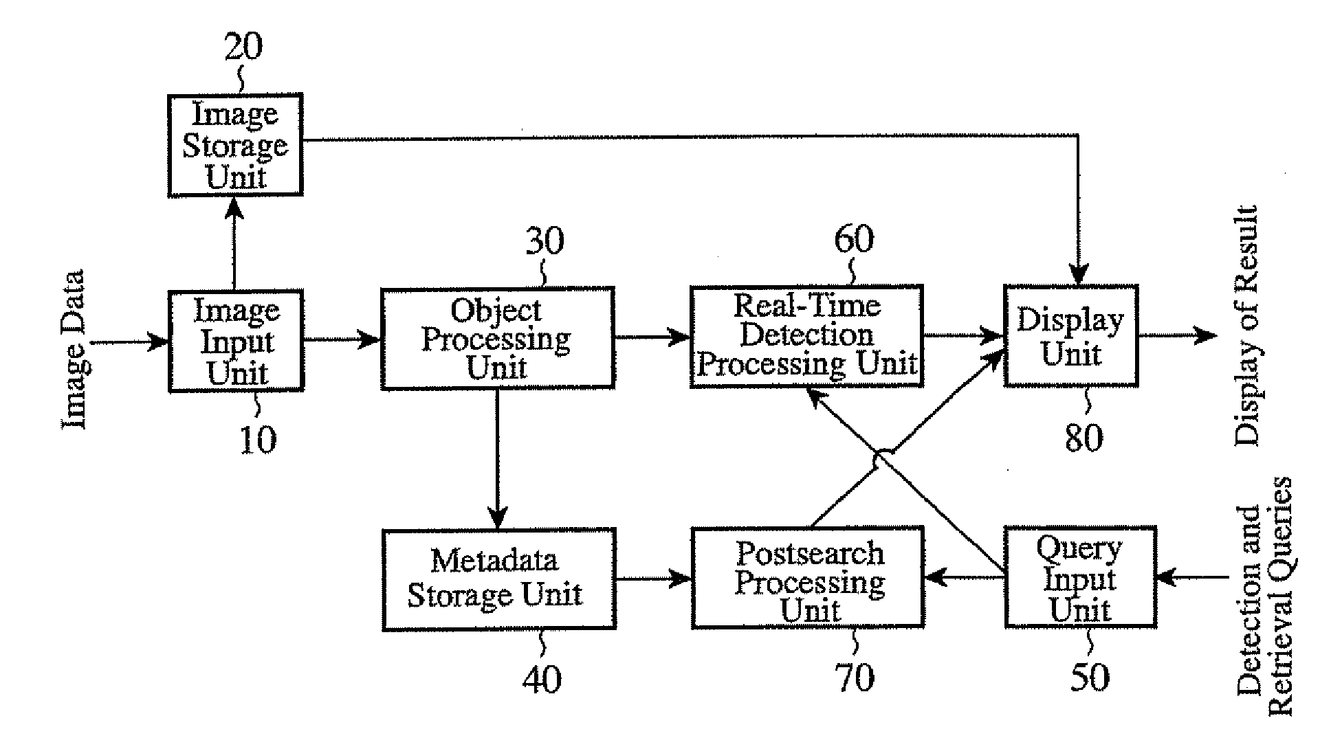
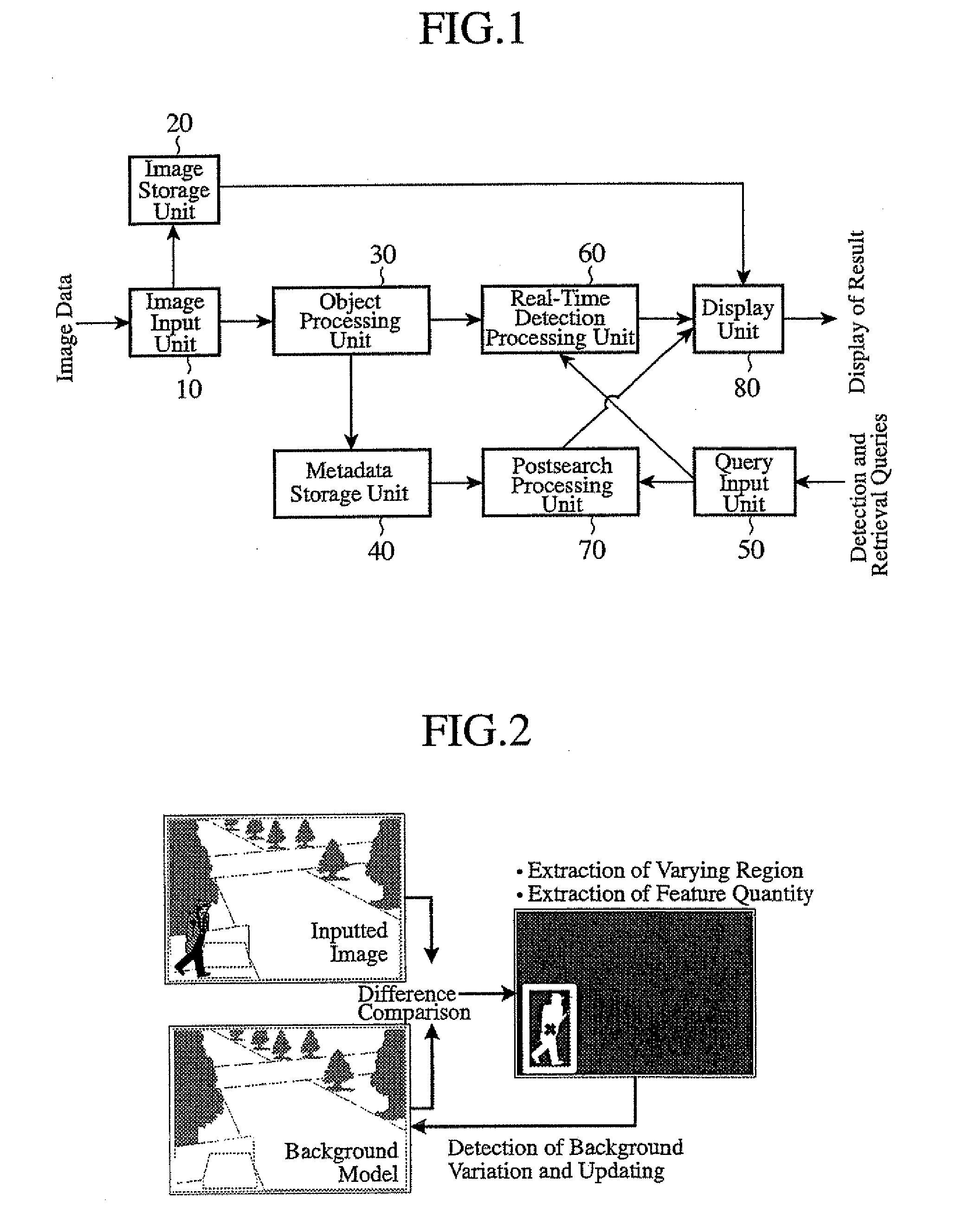
[0035]FIG. 1 is a block diagram showing the structure of an image surveillance / retrieval system in accordance with embodiment 1 of the present invention. This image surveillance / retrieval system is provided with an image input unit 10, an image storage unit 20, an object processing unit 30, a metadata storage unit 40, a query input unit 50, a real-time detection processing unit 60, a postretrieval processing unit 70, and a display unit 80. The image surveillance / retrieval system can be built in an environment where processing is carried out by a computer, such as a personal computer or a workstation. As an alternative, the image surveillance / retrieval system can be so constructed that some of the components shown in FIG. 1 exist at a physical distance from the remaining part, and sequentially carry out the processing at the remote place through a communication function, such as a LAN (Local Area Network) or a public network.

[0036]The image input unit 10 receives an input of image da...

embodiment 2

[0109]FIG. 14 is a block diagram showing the structure of an image surveillance / retrieval system in accordance with embodiment 2 of the present invention. This image surveillance / retrieval system is provided with an image input unit 10, an image storage unit 20, an object processing unit 30, a metadata storage unit 40, a query input unit 50, a real-time detection processing unit 60, a postretrieval processing unit 70, a display unit 80, and a block shape determination processing unit 100. In the image surveillance / retrieval system of this embodiment, the block shape determination processing unit 100 is added to the structure, as shown in FIG. 1, of that in accordance with above-mentioned embodiment 1, and therefore the other structure of the image surveillance / retrieval system of this embodiment is the same as the structure shown in FIG. 1.

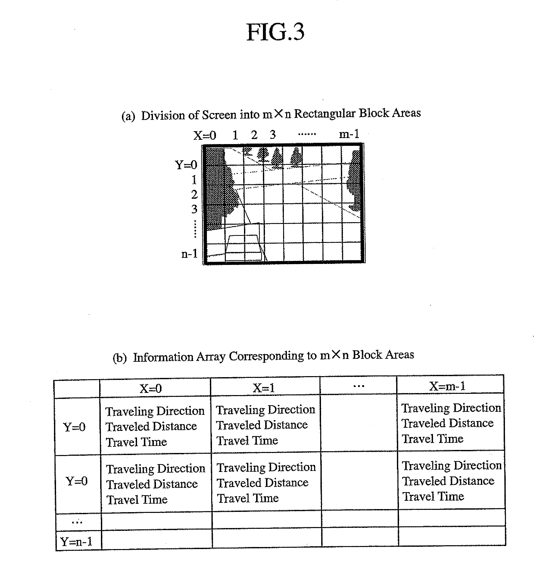
[0110]In above-mentioned embodiment 1, the image screen is divided into a total of m×n equal-sized rectangular block areas in which m rectangular...

embodiment 3

[0117]A block diagram showing the structure of an image surveillance / retrieval system in accordance with embodiment 3 of the present invention is the same as that shown in FIG. 14 of above-mentioned embodiment 2. The image surveillance / retrieval system in accordance with this embodiment 3 adjusts the size of each of the plurality of block areas according to the on-screen position of each object without putting restrictions that make all the block areas on the screen have the same size.

[0118]FIGS. 15(a) and 15(b) are diagrams showing an example of an image in which the size of each of the plurality of block areas is adjusted according the on-screen position of an object to be shot. As shown in the example of the image of FIG. 15(a) in which the object to be shot is moving in a slanting direction, when using a surveillance camera, there are actually many cases in which the optical axis of the camera forms a shallow angle with the ground surface included in the image of the object to b...


PUM


Abstract

An object processing unit divides each image frame of received image data into block areas, extracts an object from each image frame, and extracts, as metadata, the features of this object for each block area. A real-time detection processing unit compares the metadata extracted for each block area with a received real-time detection query, and detects an object which satisfies the real-time detection query. A post-retrieval processing unit compares the metadata for each block area stored in a metadata storage unit with a received post-retrieval query, and retrieves an object which satisfies the post-retrieval query.

Description

BACKGROUND OF THE INVENTION[0001]1. Field of the Invention[0002]The present invention relates to an image surveillance / retrieval system which surveils an image inputted from a surveillance camera on a predetermined condition, and which retrieves an image recorded therein according to a predetermined query.[0003]2. Description of Related Art[0004]In a prior art image surveillance system for security applications and so on for protecting persons and facilities from a suspicious person and an offender, a watcher always surveils many camera images visually for a long time with a very heavy load and with a low degree of efficiency. To solve this problem, there have been provided various ideas for extracting a scene in which a specific event occurs from an inputted image by carrying out image processing on the image, as disclosed in patent reference 3, and then providing information to attract the attention of the watcher for the watcher. To be more specific, there have been provided an i...

Claims


Application Information

Patent Timeline
Patent Type & Authority Applications(United States)
IPC IPC(8): G06K9/00
CPCG06F17/30265G06K9/00771G06T7/004G08B13/19671G06T2207/30241G08B13/19608G06T7/2033G06T7/70G06T7/246G06F16/58G06V20/52H04N7/18G06F16/583
Inventor SATO, KAZUYAHAGA, TETSUJI
Owner MITSUBISHI ELECTRIC CORP
Why Eureka
Try Eureka