Optical Film, Polarizing Plate And Image Display Using The Same

a technology of optical film and polarizing plate, applied in the field of optical film, can solve the problems of affecting the film strength and adhesion, and affecting the performance of the coating film, etc., and achieves excellent scratch resistance, antifouling property and antistatic property, and high visibility.

Active Publication Date: 2007-10-25
FUJIFILM CORP
View PDF5 Cites 18 Cited by
  • Summary
  • Abstract
  • Description
  • Claims
  • Application Information

AI Technical Summary

Benefits of technology

[0035] An optical film of the present invention is assured of reflectance low enough to suppress glaring and excellent in the scratch resistance, antifouling property and antistatic property. Also, a display comprising the optical film of the present invention or a polarizing plate using an optical film of the present invention has the above-described properties, less causes reflection of outside light or projection of surrounding scenes, and ensures very high visibility.

Problems solved by technology

In particular, the coating composition containing fine particles having a particle size of 1 μm or less has a large specific area and therefore, aggregation is liable to occur in the process of drying the organic solvent due to strong interaction between fine particles.
As a result, aggregation or phase separation may be caused in the coating film and this may adversely affect the performance of the coating film.
The means for reducing the refractive index of a material includes introduction of a fluorine atom and reduction of the density (introduction of voids), but either means tends to impair the film strength and adhesion and decrease the scratch resistance.
Thus, it has been difficult to achieve both low refractive index and high scratch resistance.
This means is effective to a certain extent for the improvement of scratch resistance, but in the case of a film substantially lacking in the film strength and interface adhesion, sufficiently high scratch resistance cannot be obtained only by this means.
However, the silane coupling agent having a low boiling point disadvantageously volatilizes and dissipates in the coating and drying steps and needs to be added in an excess amount by taking into account the volatilization loss.
Thus, there is a problem that a stable performance is difficult to obtain.

Method used


Image

  • Optical Film, Polarizing Plate And Image Display Using The Same
  • Optical Film, Polarizing Plate And Image Display Using The Same
  • Optical Film, Polarizing Plate And Image Display Using The Same

Examples


example 1

[0272] The present invention is described below by referring to Examples, but the present invention is not limited thereto. Unless otherwise indicated, the “parts” and “%” are on the mass basis.

[0273] A multilayer antireflection film shown below was produced.

(Preparation of Coating Solution for Hardcoat Layer)

[0274] The following composition was charged into a mixing tank and stirred to prepare a coating solution for hardcoat layer.

[0275] 270.0 Parts by mass of poly(glycidyl methacrylate) having a weight average molecular weight of 15,000, 730.0 parts by mass of methyl ethyl ketone, 500.0 parts by mass of cyclohexanone and 50.0 parts by mass of a photopolymerization initiator (Irgacure 184, produced by Ciba Specialty Chemicals) were added to 750.0 parts by mass of trimethylolpropane triacrylate (TMPTA, produced by Nippon Kayaku Co., Ltd.) and stirred. The resulting solution was filtered through a polypropylene-made filter having a pore size of 0.4 μm to prepare a coating soluti...

example 2

[0334] Samples were produced by changing the inorganic fine particle and the solvent composition of the low refractive index layer in Sample 104 of Example 1 as shown in Table 2. As for the solvent composition, at the time of adjusting the solid content concentration of the entire coating solution to 6 mass %, the adjustment was performed by changing the amount of cyclohexanone. The following silica Particles were used.

(Preparation of Liquid Dispersion A-2)

[0335] Dispersion A-2 was prepared thoroughly in the same manner as Liquid Dispersion A-1 except for decreasing the amount of acryloyloxypropyltrimethoxysilane to 20 parts and newly adding 10 parts of tridecafluorooctyltrimethoxysilane (produced by GE Toshiba Silicones Co., Ltd.). Generation of foreign matters in the liquid dispersion was not observed and when the solid content concentration was adjusted to 20 mass % with methyl ethyl ketone, the viscosity was 5 mPa·s at 25° C. The residual isopropyl alcohol amount in the obtai...

example 3

[0341] A multilayer antireflection film shown below was produced.

(Preparation of Coating Solution A for Hardcoat Layer)PET-30 50.0 gIrgacure 184 2.0 gSX-350 (30%) 1.5 gCrosslinked acryl-styrene particle (30%) 13.9 gFP-1320.075 gKBM-5103 10.0 gToluene 38.5 g

[0342] The mixed solution above was filtered through a polypropylene-made filter having a pore size of 30 μm to prepare a coating solution for hardcoat layer.

[0343] The compounds used are shown below.

PET-30:

[0344] A mixture of pentaerythritol triacrylate and pentaerythritol tetraacrylate (produced by Nippon Kayaku Co., Ltd.).

Irgacure 184:

[0345] A polymerization initiator (produced by Ciba Specialty Chemicals).

SX-350:

[0346] A crosslinked polystyrene particle having an average particle diameter of 3.5 μm (refractive index: 1.60, produced by The Soken Chemical & Engineering Co., Ltd., a 30% toluene liquid dispersion, used after dispersion by a polytron disperser at 10,000 rpm for 20 minutes).

Crosslinked Acryl-Styrene Pa...


PUM

PropertyMeasurementUnit
refractive indexaaaaaaaaaa

Abstract

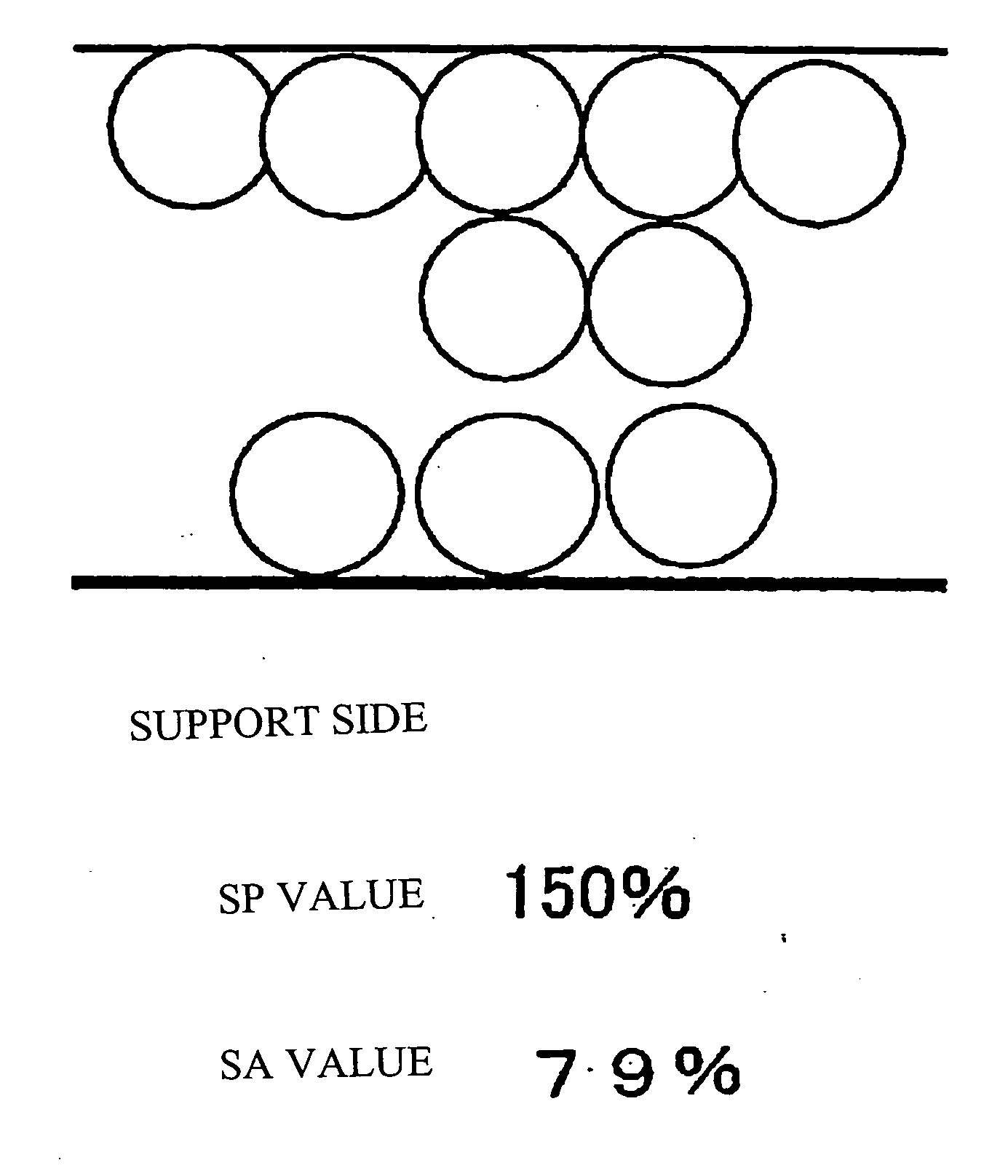
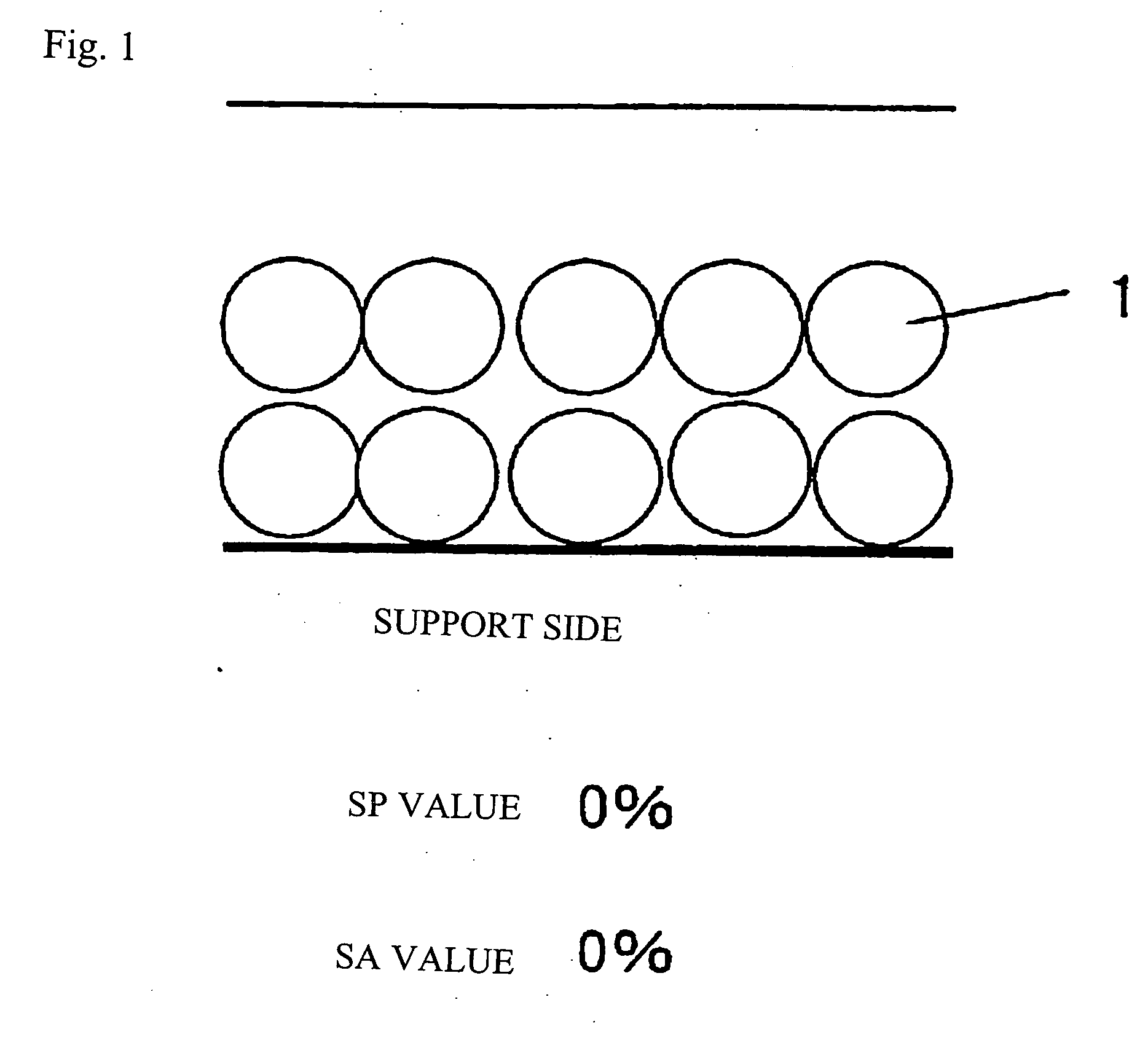
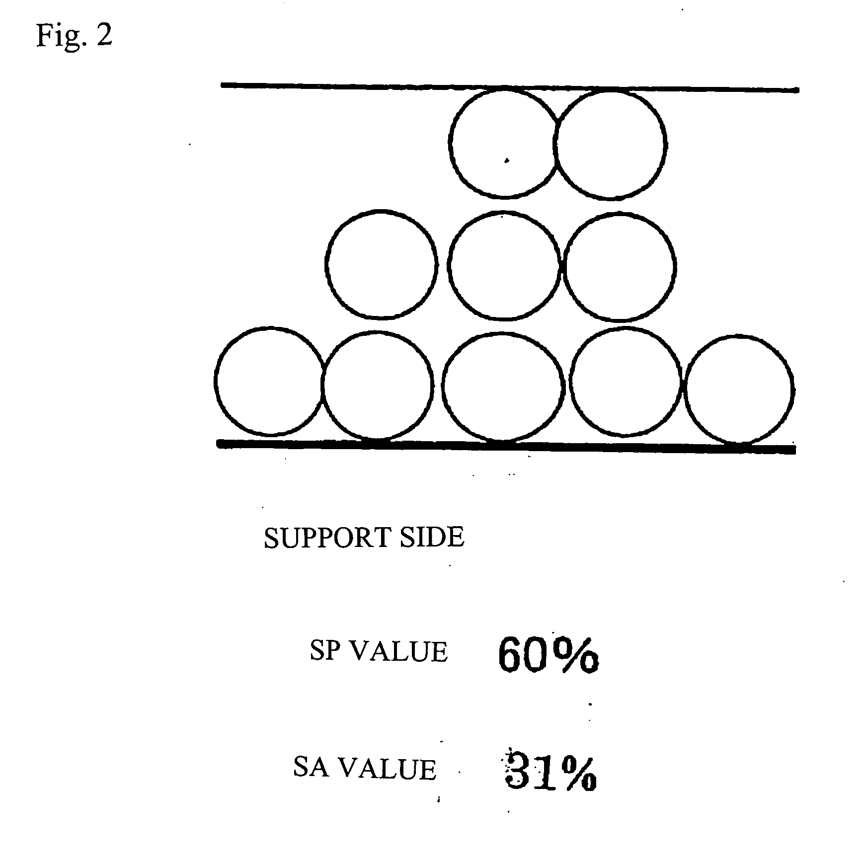
An object of the present invention is to provide an optical film assured of reflectance low enough to suppress glaring and excellent in the scratch resistance, antifouling property and antistatic property, and another object is to provide a polarizing plate and a display, using such an antireflection film. These objects can be attained by an optical film, particularly, an antireflection film, containing a support and a thin film layer formed by coating a composition containing fine particles and a binder, in which the SP value ((B/A)×100)) which is a ratio of an average particle filling factor (B) in the region of 30% of the film thickness on the upper side opposite the support to an average particle filling factor (A) in the entirety of the thin film layer is 90% or less; and a polarizing plate and an image display, using the optical film.

Description

TECHNICAL FIELD [0001] The present invention relates to an optical film, particularly, an antireflection film, and also relates to a polarizing plate and an image display. BACKGROUND ART [0002] In the case of blending fine particles and a binder and using the blend for usage such as adhesive, exterior paint, hardcoat and antireflection film, studies are being made to enhance scratch resistance, strength of the cured product, adhesion to another material contacted, and the like. [0003] In blending fine particles and a binder, it is necessary not to cause unnecessary aggregation of an inorganic material of the fine particles. One of the methods employed in general is a method of dispersing fine particles in a solvent having affinity for a binder, mixing the dispersion with a binder, and forming a film. In order to obtain a stable performance, the matter of importance is that the fine particles are stably dispersed in the solvent. Specifically, control of hydrophilicity, hydrophobicity...

Claims


Application Information

Patent Timeline
Patent Type & Authority Applications(United States)
IPC IPC(8): G02B1/10G02B5/30G02B1/11
CPCG02B1/105Y10T428/1059G02B1/111G02B5/3025Y10T428/265Y10T428/1073Y10T428/2495Y10T428/269Y10T428/24942Y10T428/2991Y10T428/257Y10T428/259Y10T428/256Y10T428/26Y10T428/25G02B1/11Y10T428/31663Y10T428/3154G02B1/16C09K2323/055C09K2323/05G02B1/10G02B5/30G02B1/14
Inventor YONEYAMA, HIROYUKIINOUE, KATSUMIIKEDA, AKIRASUZUKI, SATOMI
Owner FUJIFILM CORP
Why Eureka
Try Eureka