Blood Pump-Oxygenator System

a blood pump and oxygenator technology, applied in the field of compact artificial pump lung system, can solve the problems of general complexity of operation, exacerbating acute respiratory insufficiency in many patients, and conventional oxygenator system

Inactive Publication Date: 2007-10-25
UNIV OF MARYLAND BALTIMORE
View PDF8 Cites 26 Cited by
  • Summary
  • Abstract
  • Description
  • Claims
  • Application Information

AI Technical Summary

Problems solved by technology

Often, however, the tidal volumes, airway pressure, and oxygen fraction necessary to achieve sufficient gas exchange with these therapies can cause further damage to the lungs creating ventilator-induced lung injury, including barotrauma, volutrauma, and other iatrogenic injuries, further exacerbating acute respiratory insufficiency in many patients.
Conventional oxygenator systems can also be associated with such problems as a general complexity of operation, thrombosis, blood trauma, infection, bleeding due to the need for high levels of anticoagulation, and limited mobility of the patient.
Drawbacks associated with these integrated pump-oxygenators include, however, non-uniform blood flow through fiber membranes and the existence of laminar boundary flow zones between blood cells and fiber membranes.
The non-uniform blood flow across the fiber membranes, in this regard, results in hyper- and hypo-perfusion of the blood in flow paths.
Hyper-perfusion is defined as exposure of oxygen-saturated blood to oxygenator fibers, which does not grant any additional benefit yet exposes blood unnecessarily to elevated shear stress and synthetic material contact.
Unfortunately, these are the major contributing factors to blood activation and, consequently, to thrombosis formation.
Thus, gas transfer efficiency is significantly hindered by the existence of the boundary layer.
This results in the relative motion of membrane surfaces to the blood cells, which can cause the pumping of blood and oxygenation of the blood to occur simultaneously and can disrupt the buildup of the boundary layers around the gas-exchange surface.

Method used


Image

  • Blood Pump-Oxygenator System
  • Blood Pump-Oxygenator System
  • Blood Pump-Oxygenator System

Examples


Embodiment Construction

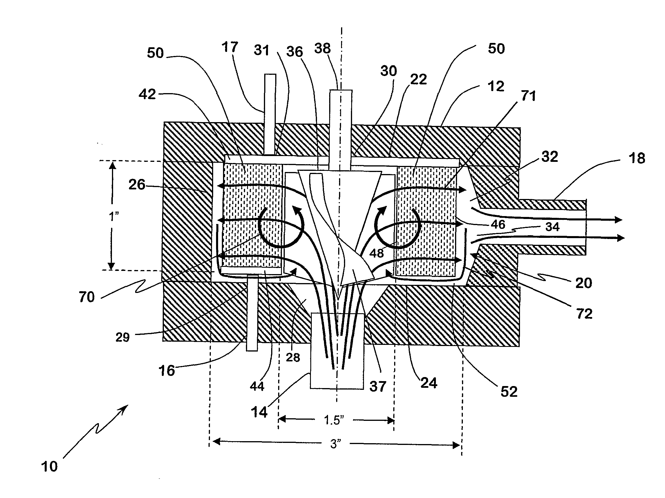
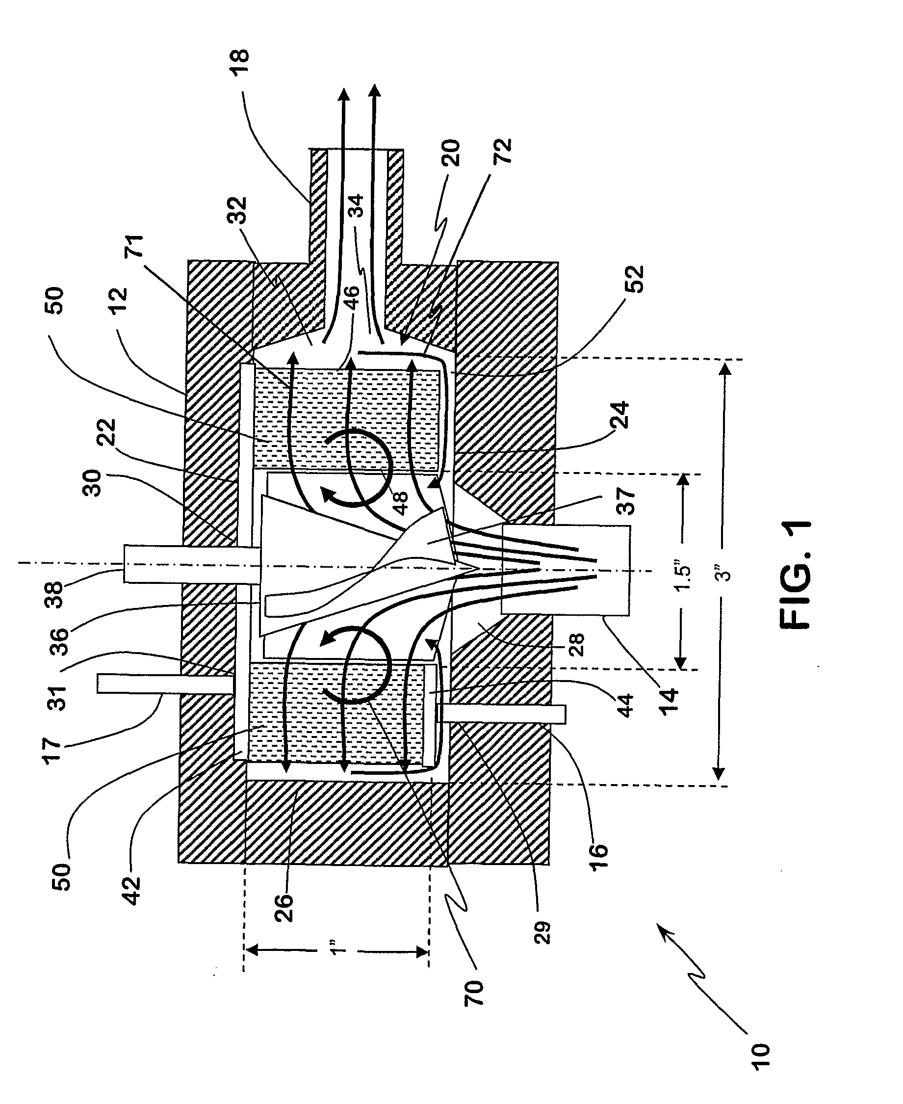
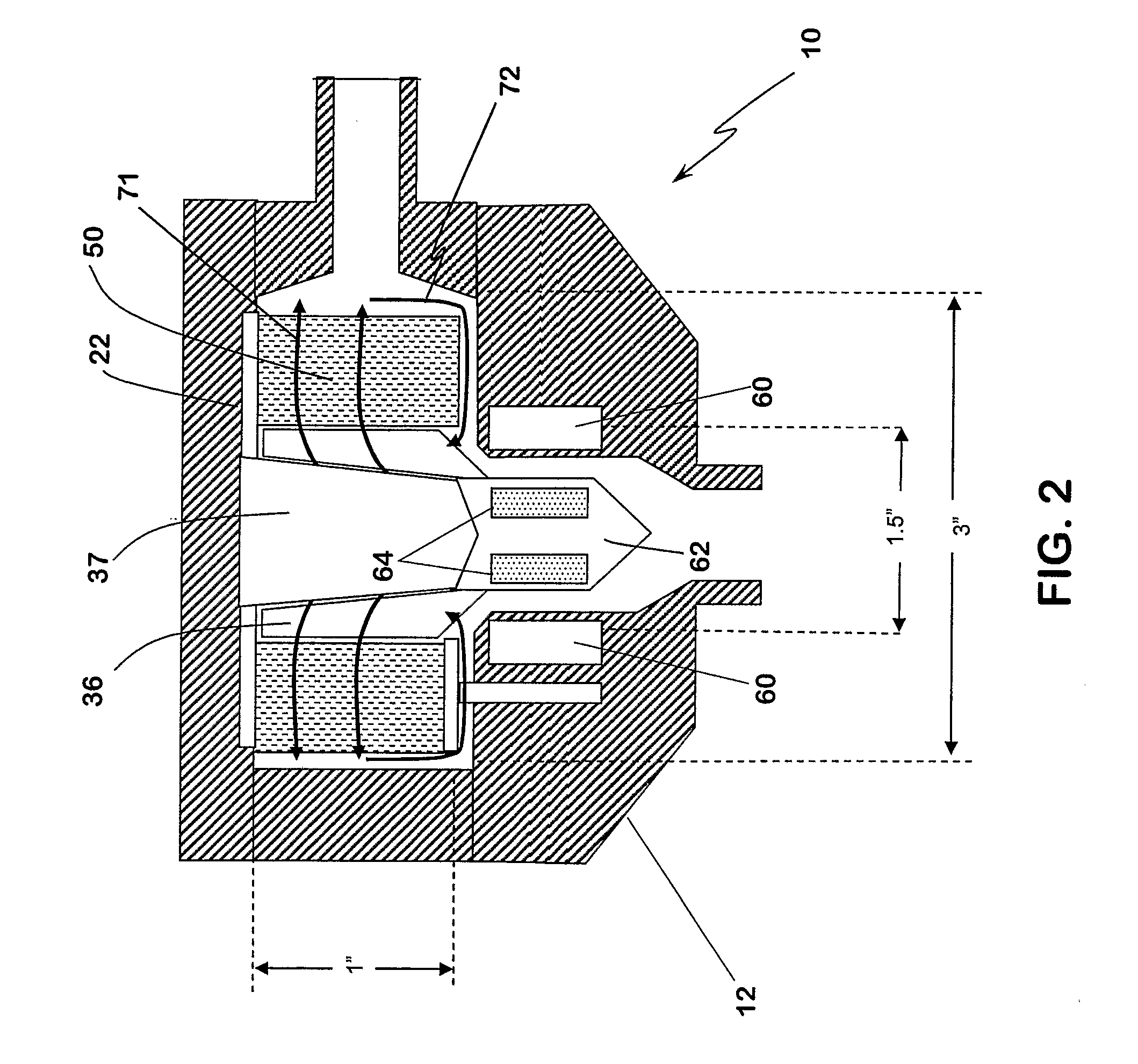
[0016] The present invention provides a system comprising a housing, an impeller disposed within the housing, and a fiber bed disposed between an inner wall of the housing on the impeller. A bypass channel is defined by a wall of the housing and an outer periphery of the fiber bed, wherein the bypass channel provides a path for blood to be recirculated through the fiber bed. Another blood pump-oxygenator system is also provided. The system comprises a housing, a means for drawing blood into the housing, a means for removing carbon dioxide from the blood, a means for adding oxygen to the blood, and a means for recirculating the blood back through the removing means and the adding means.

[0017]FIG. 1 illustrates a blood pump-oxygenator system in accordance with an embodiment of the present invention. In particular, the system 10 includes a generally cylindrical housing 12, which includes a blood inlet 14, an oxygen inlet 16, a carbon dioxide outlet 17 and a blood outlet 18. Although t...


PUM


Abstract

A blood pump-oxygenator system including a housing, an impeller, a fiber bed, and a bypass channel that provides a path for blood to be recirculated through the fiber bed; a system comprising a housing, a means for drawing blood into the housing, a means for removing carbon dioxide from the blood, a means for adding oxygen to the blood, and a means for recirculating the blood back through the removing means and the adding means; and a method for oxygenating blood comprising drawing blood into a housing comprising a fiber bed, propelling blood principally in a radial direction through the fiber bed, adding oxygen to the blood as it moves through the fiber bed, and repeating the forcing and adding steps for at least a portion of the blood.

Description

CROSS-REFERENCE TO RELATED PATENT APPLICATIONS [0001] This patent application claims the benefit of U.S. Provisional Patent Application No. 60 / 609,411, filed Sep. 13, 2004.FIELD OF THE INVENTION [0002] This invention relates to a compact artificial pump-lung system, more specifically an integrated pump and oxygenator that can be implanted in the body or externally as a paracorporeal heart-lung to provide respiratory support for patients with lung diseases or used as a heart-lung machine for cardiopulmonary support during open-heart surgery. BACKGROUND OF THE INVENTION [0003] Lung disease is the third largest cause of death in the United States, accounting for approximately 1 out every 7 adult deaths. In fact, an estimated 30 million Americans are now living with chronic lung disease. Adult respiratory distress syndrome (ARDS), in this regard, afflicts approximately 150,000 patients annually in the U.S., and despite advances in critical care, mortality remains between 40% and 50%. [0...

Claims


Application Information

Patent Timeline
Patent Type & Authority Applications(United States)
IPC IPC(8): A61M37/00A61M60/113A61M60/122A61M60/226A61M60/38A61M60/422A61M60/825
CPCA61M1/101A61M1/1678A61M1/1031A61M1/1006A61M1/1017A61M1/1698A61M1/262A61M1/267A61M60/824A61M60/113A61M60/422A61M60/148A61M60/38A61M60/825A61M60/226A61M60/122A61M1/3623
Inventor WU, ZHONGJUNANTAKI, JAMES F.GRIFFITH, BARTLEY P.
Owner UNIV OF MARYLAND BALTIMORE
Why Eureka
Try Eureka