Flip-chip flow sensor

a flow sensor and flip-chip technology, applied in the direction of positive temperature coefficient thermistors, liquid/fluent solid measurement, instruments, etc., can solve the problems of wire bonds, flow interaction, corrosion, etc., to reduce the sensitivity of flow sensors, and improve the accuracy. the effect of accuracy

Inactive Publication Date: 2007-11-01
HONEYWELL INT INC
View PDF23 Cites 23 Cited by
  • Summary
  • Abstract
  • Description
  • Claims
  • Application Information

AI Technical Summary

Benefits of technology

[0009] The substrate material can have high thermal conductance. Ideally, heat can flow through the membrane easily. Heat flowing through the rest of the substr

Problems solved by technology

Additionally, wire bonds made on the surface exposed to the gas or liquid bein

Method used


Image

  • Flip-chip flow sensor
  • Flip-chip flow sensor
  • Flip-chip flow sensor

Examples


Embodiment Construction

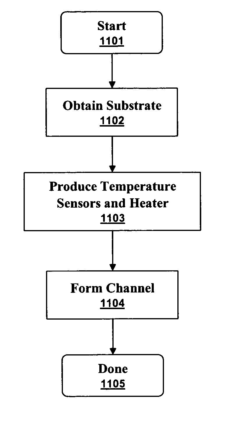
[0022] The particular values and configurations discussed in these non-limiting examples can be varied and are cited merely to illustrate at least one embodiment and are not intended to limit the scope thereof. In general, the figures are not to scale.

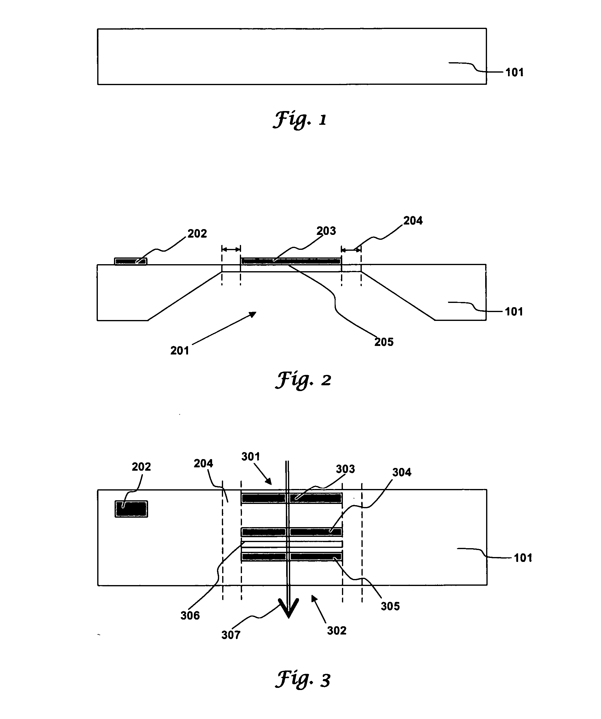
[0023]FIG. 1 illustrates a side view of a substrate 101 in accordance with aspects of the embodiments. The substrate can be a wafer of silicon, glass, quartz, or another material as are commonly used in semiconductor manufacturing.

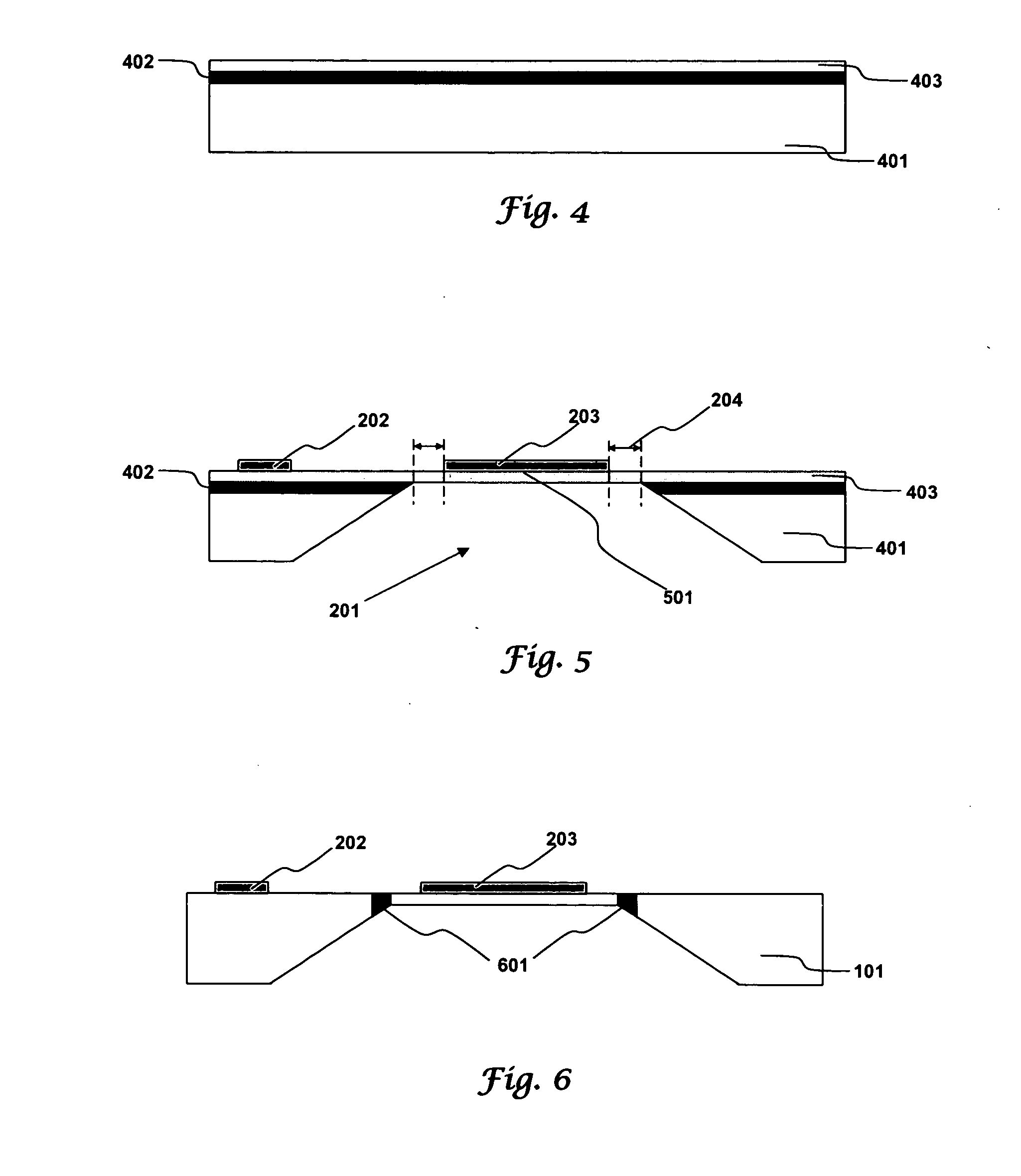
[0024]FIG. 2 illustrates a side view of a flow sensor in accordance with aspects of the embodiments. A channel 201 in the bottom of the substrate 101 is separated from the substrate top by a membrane 205. A substrate temperature sensor 202 is positioned away from the channel 201. Other sensor elements 203 are on top of the membrane 205. An inset distance 204 separates the sensor elements 203 from the edge of the channel 201.

[0025] The membrane must be thick enough to be physically robust and thin enough to...


PUM


Abstract

A flip-chip flow sensor has electrical components, such as temperature sensors and a heater, on the top of a substrate and has a channel formed in the bottom of the substrate. The channel is separated from the substrate's top by a membrane of substrate material. A fluid flowing through the channel is separated from a heater, upstream temperature sensor, downstream temperature sensor, bond pads, and wire bonds by the membrane. Heat flows through the membrane easily because the membrane is thin. As such, the electrical elements of the flow sensor, the bond pads and the wires are physically separated from a fluid flowing through the channel but can function properly because they are not thermally isolated.

Description

TECHNICAL FIELD [0001] Embodiments relate to flow sensors and sensor systems. Embodiments also relate to using temperature sensors on either side of a heater to measure fluid flows. BACKGROUND OF THE INVENTION [0002] The measurement of fluid flows is important in manufacturing, medicine, environmental monitoring, and other areas. One type of flow sensor measures the rise in temperature of a fluid flowing past a heater. Smaller temperature rises correspond to faster flow. Gases and liquids are both fluids and their flow rates can be measured by flow sensors that include temperature sensors and heaters. [0003] Current technology provides systems and methods for producing temperature sensors and heaters on substrates using well-established semiconductor processing techniques. Those skilled in the art of semiconductor manufacturing are familiar with these system and methods such as photolithography, deposition, vapor deposition, etch, wet etch, plasma etch, reactive ion etch, as well as...

Claims


Application Information

Patent Timeline
IPC IPC(8): G01F25/00
CPCG01F1/6847G01F1/6845
Inventor BECK, SCOTTMORALES, GILBERTO
Owner HONEYWELL INT INC
Why Eureka
Try Eureka