
Solar Inverter and Photovoltaic Installation Comprising Several Solar Inverters

a solar inverter and photovoltaic technology, applied in the field of solar inverters, can solve problems such as the need for separate monitoring devices

Inactive Publication Date: 2007-11-01
SIEMENS AG
View PDF17 Cites 86 Cited by
  • Summary
  • Abstract
  • Description
  • Claims
  • Application Information

AI Technical Summary

Benefits of technology

[0028] This is associated with the major advantage that firstly the signaling module can be implemented extremely compactly since the electronic components and fuinctional assemblies required for monitoring the respective solar inverters are not required. It is also possible to fashion the signaling module in such a way that said module has an electronic display for presenting the pieces of status information that are sent by the respective solar inverters on a cyclical basis. If the signaling module additionally has input keys, different pieces of status information to be displayed can also be selected.
[0029] In a particularly advantageous embodiment of the photovoltaic installation, the signaling module has electronic means, such as a simple microcontroller for example, in order to convert the error message received from the respective solar inverters into a corresponding e-mail message, fax or SMS text message.
[0030] This is associated with the advantage that the error message can be transferred promptly and in plaintext, directly on the spot, to a responsible person. It is particularly advantageous if the error message is forwarded as plaintext to a mobile telephone that the person to be monitored usually carries with him / her.

Problems solved by technology

A disadvantage of the first solution described is the fact that a separate monitoring device has to be provided, which represents an additional investment for the operator of a photovoltaic installation.
A disadvantage of the second solution is the fact that an additional PC with a special software application is needed to be able to carry out a regular check on the installation.

Method used


Image

  • Solar Inverter and Photovoltaic Installation Comprising Several Solar Inverters
  • Solar Inverter and Photovoltaic Installation Comprising Several Solar Inverters

Examples


Embodiment Construction

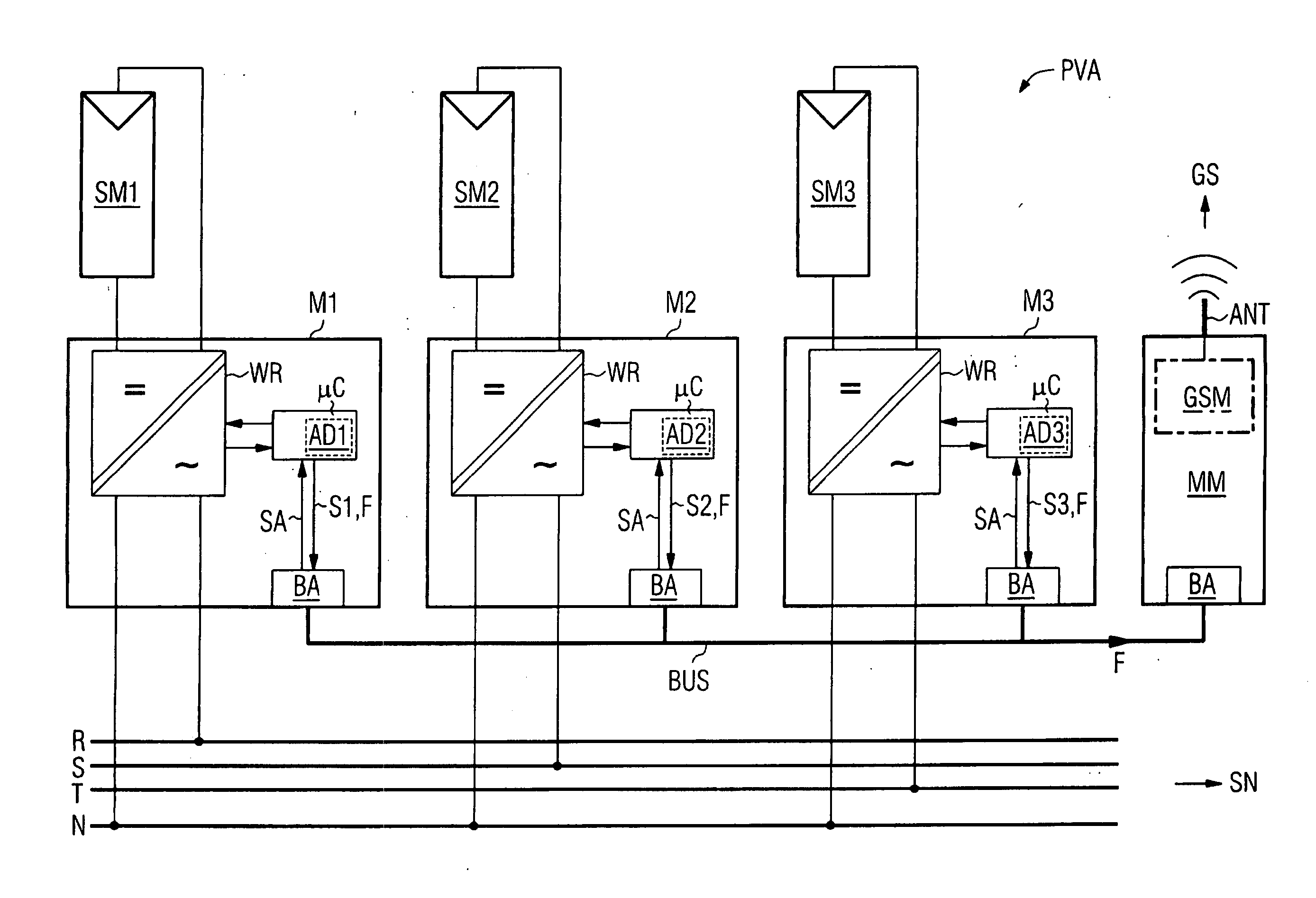
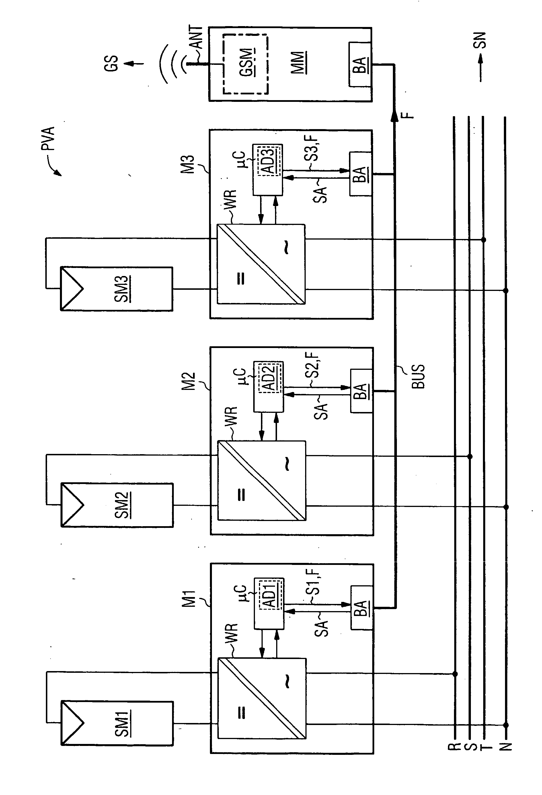
[0033] In this arrangement the figure shows a photovoltaic installation PVA according to the invention which has, by way of example, three photovoltaic generators SM1-SM3. For reasons of clarity, their internal structure is not represented in further detail. In this case the photovoltaic generators SM1-SM3 provide a feed into one solar inverter M1-M3 each. In the example in the figure, each solar inverter M1-M3 has an inverter module WR which is connected to a photovoltaic generator SM1-SM3 at the input end. In this case the solar direct current is converted into a single-phase alternating voltage. For safety reasons, this voltage can, as already occurs in the present example, be potential-free with respect to the voltage level of the photovoltaic generators SM1-SM3.

[0034] In the example in the figure, the three solar inverters M1-M3 provide a feed into one phase R, S, T each of a power system SN in order to achieve a roughly even power distribution in said system SN. A system SN o...


PUM


Abstract

In one aspect, a solar inverter which can be connected to at least one photovoltaic generator at the input end and to a power system at the output end is provided. The solar inverter includes an inverter module, an electronic control unit at least for diagnosing an inverter module, and a bus interface for technically connecting the electronic control unit to a communication bus. The electronic control unit cyclically outputs a piece of status information of the solar inverter on the communication bus, and outputs an error message on the communication bus, cyclically reads status information of other solar inverters that are connected to the communication bus, and outputs an error message on the communication bus in case at least one expected additional piece of status information fails to be output. Whereby, the need for a separate monitoring unit is eliminated.

Description

CROSS REFERENCE TO RELATED APPLICATIONS [0001] This application is the US National Stage of International Application No. PCT / EP2005 / 005678, filed May 25, 2005 and claims the benefit thereof. The International Application claims the benefits of German application No. 102004025924.0 filed May 27, 2004, both of the applications are incorporated by reference herein in their entirety. FIELD OF INVENTION [0002] The invention relates to a solar inverter which can be connected to at least one photovoltaic generator at the input end and to a power system, in particular a public power system, at the output end and has at least one inverter module, an electronic control unit, at least for carrying out diagnostics on an inverter module, and a bus interface for establishing a data processing connection between the electronic control unit and a communication bus. [0003] The invention relates to a photovoltaic installation for effecting a feed into a power system, in particular a public power sys...

Claims


Application Information

Patent Timeline
Patent Type & Authority Applications(United States)
IPC IPC(8): G08B21/00H02M7/00H02J3/38H02J13/00H02M7/44H02N6/00
CPCH02J13/0062H02M7/493Y02E40/72Y04S10/123H02J3/383Y02E10/563H02J2300/24H02J3/381H02J13/00016Y02E10/56Y02E40/70Y04S40/124Y02E60/00H02M7/521H02M7/48H02J7/35
Inventor BURGER, ROLAND
Owner SIEMENS AG
Learn More