MIMO-OFDM transmitter
Inactive Publication Date: 2007-11-01
FUJITSU LTD
19 Cites 76 Cited by
AI-Extracted Technical Summary
Problems solved by technology
Further, a length of the OFDM symbol is relatively long, resulting in a less...
Benefits of technology
[0029]According to the present invention, the data transmission efficiency can...
Abstract
It is an object to improve data transmission efficiency by reducing a length of time required for transmitting pilot signals.
A MIMO-OFDM transmitter has a plurality of transmitting antennas transmitting OFDM signals to a receiver, and a generating unit generating direct spreading pilot signals of which pilot data for demodulating the OFDM signals transmitted from the plurality of transmitting antennas in the receiver are spread with direct spreading codes, and transmitting the direct spreading pilot signals from the plurality of transmitting antennas.
Application Domain
Modulated-carrier systemsMultiplex communication +4
Technology Topic
Data transmissionPilot signal +3
Image
Examples
- Experimental program(4)
Example
First Embodiment
[0051]A system, which combines MIMO with OFDM in a first embodiment, is configured by a MIMO-OFDM transmitter having a plurality of transmitting antennas and a MIMO-OFDM receiver having a plurality of receiving antennas as illustrated in FIG. 19 in the prior art.
[0052]<>
[0053]FIG. 1 is a diagram showing the MIMO-OFDM transmitter in the first embodiment of the present invention. The MIMO-OFDM transmitter in the first embodiment includes a serial/parallel converting unit 101, an inverse fast Fourier transform operation unit 102, a plurality of OFDM data signal transmitting units 120, a direct spreading pilot signal transmitting unit 130 and a plurality of transmitting antennas 107. The OFDM data signal transmitting units 120 has a guard interval inserting unit 103, a digital/analog converting unit 104, an up-converting unit 105 and an amplifier 106. The direct spreading pilot signal transmitting unit 130 has a direct spreading pilot signal generating unit.
[0054]The serial/parallel converting unit 101 converts inputted channel data into a frequency domain data of a subcarrier. The serial/parallel converting unit 101 outputs the frequency domain data to the inverse fast Fourier transform operation unit 102. The inverse fast Fourier transform (IFFT) operation unit 102 inverse-Fourier-transforms the inputted frequency domain data into time domain data. The inverse fast Fourier transform operation unit 102 outputs the time domain data to the OFDM data signal transmitting unit 120 for every transmitting antenna.
[0055]The time domain data inputted to the OFDM data signal transmitting unit 120 per transmitting antenna is inputted to the guard interval inserting unit 103. The guard interval inserting unit 103 attaches (inserts), as a guard interval, part of data of the trailing portion of the time domain to the head (of a symbol). The data attached with the guard interval is defined as an OFDM symbol. The insertion of the guard interval (guard period) can reduce influence of interference, caused by multi-paths, between the OFDM symbols. The guard interval inserting unit 103 outputs the OFDM symbol to the digital/analog converting unit 104. The digital/analog converting unit 104 converts the OFDM symbol inputted from the guard interval inserting unit 103 into analog signals, and outputs the analog signals to the up-converting unit 105. The up-converting unit 105 up-converts the inputted analog signals into high-frequency signals. The amplifier 106 amplifies the high-frequency signals and transmits the amplified signals from the respective antennas 107.
[0056]In the direct spreading pilot signal transmitting unit 130, the direct spreading pilot signal generating unit generates direct spreading pilot signals (DS-Pilot), and these pilot signals are transmitted from the respective transmitting antennas.
[0057]FIG. 2 is a diagram showing the direct spreading pilot signal generating unit 500 in the direct spreading pilot signal transmitting unit 130 on the transmitting side. The MIMO-OFDM transmitter in the first embodiment further includes the direct spreading pilot signal generating unit 500.
[0058]The direct spreading pilot signal generating unit 500 includes a direct spreading code generating unit 510, a multiplying unit 503 that multiplies, by pilot data, the direct spreading code generated by the direct spreading code generating unit 510, and a guard interval inserting unit 505. The direct spreading pilot signals generated by the direct spreading pilot signal generating unit 500 are transmitted from individual transmitting antennas 530.
[0059]The direct spreading code generating unit 510 generates individual direct spreading codes (Code #0 through Code #N−1) for every transmitting antenna. The multiplying unit 503 multiplies, by the pilot data (the known signal), the direct spreading code per transmitting antenna, which has been generated by the direct spreading code generating unit 510, and outputs a result thereof to the guard interval inserting unit 505. The pilot data can involve using data different for every transmitting antenna and also data that is the same with all of the transmitting antennas. The guard interval inserting unit 505 attaches (inserts), as the guard interval, part of the tailing portion of the inputted signal to the signal (symbol), thereby organizing the direct spreading pilot signal (pilot symbol). Further, a scheme of attaching none of the guard interval is also available.
[0060]The direct spreading pilot signals generated by the direct spreading pilot signal generating unit 500 are transmitted simultaneously from the respective transmitting antennas 530.
[0061]FIG. 3 is a diagram showing a transmission timing of the pilot signals in the first embodiment. Each transmitting antenna is capable of reducing a period of transmitting time of the pilot signals in order to transmit the direct spreading pilot signals simultaneously.
[0062]<>
[0063]FIG. 4 is a diagram illustrating the MIMO-OFDM receiver in the first embodiment of the present invention. The MIMO-OFDM receiver in the first embodiment includes a plurality of receiving antennas 201, OFDM data signal receiving units 220, a fast Fourier transform operation unit 207, a channel estimation unit 208 and a parallel/serial converting unit 209.
[0064]The data signals received by the respective receiving antennas 201 are inputted to the OFDM data signal receiving units 220 corresponding to the individual receiving antennas 201. The data signals inputted to the OFDM data signal receiving units 220 are inputted to a down-converting unit 202. The down-converting unit 202 down-converts the high-frequency signals transmitted from the transmitter and received by the receiving antennas 201. An AGC (Auto Gain Control) amplifier 203 amplifies the down-converted reception signals. An analog/digital converting unit 204 converts the amplified reception signals into digital signals. A symbol timing detection unit 205 detects the timing of the OFDM symbol from the guard interval (GI). A guard interval removing unit 206 removes the guard intervals inserted by the transmitter from the digital signals. The data signals, of which the guard intervals have been removed, are inputted to the fast Fourier transform operation unit 207.
[0065]The fast Fourier transform (FFT) operation unit 207 transforms the digital signals in the time domain into a plurality of subcarrier signals in the frequency domain. The channel estimation unit 208 makes channel estimation per subcarrier by use of the data outputted from a direct spreading pilot signal receiving unit 230. A channel estimation value obtained by the channel estimation unit 208 is multiplied by the output of the fast Fourier transform operation unit 207, thereby correcting a channel fluctuation. The parallel/serial converting unit 209 converts the corrected parallel data into the serial data, thereby obtaining the serial channel data.
[0066]FIG. 5 is a diagram illustrating an example of a configuration for receiving the direct spreading pilot signals based on the separate direct spreading codes given from the respective antennas The MIMO-OFDM receiver in the first embodiment further includes a direct spreading pilot signal receiving unit 600.
[0067]The direct spreading pilot signal receiving unit 600 has a guard interval removing unit 605 and a plurality of matched filters 603 corresponding to the direct spreading codes of the respective transmitting antennas.
[0068]The guard interval removing unit 605 removes the guard intervals from the signals received by the receiving antennas 630, and outputs the signals to the matched filters 603. The plurality of matched filters 603 wait for the signals with the direct spreading codes corresponding to the respective transmitting antennas. When the reception signals are inputted to these matched filters 603, a delay profile of each transmitting antenna is obtained by a despreading process based on a replica of the spreading code. This delay profile is outputted to the channel estimation unit 208. A channel estimation value of each transmitting antenna can be calculated from the delay profile of each transmitting antenna.
Operation and Effect in First Embodiment
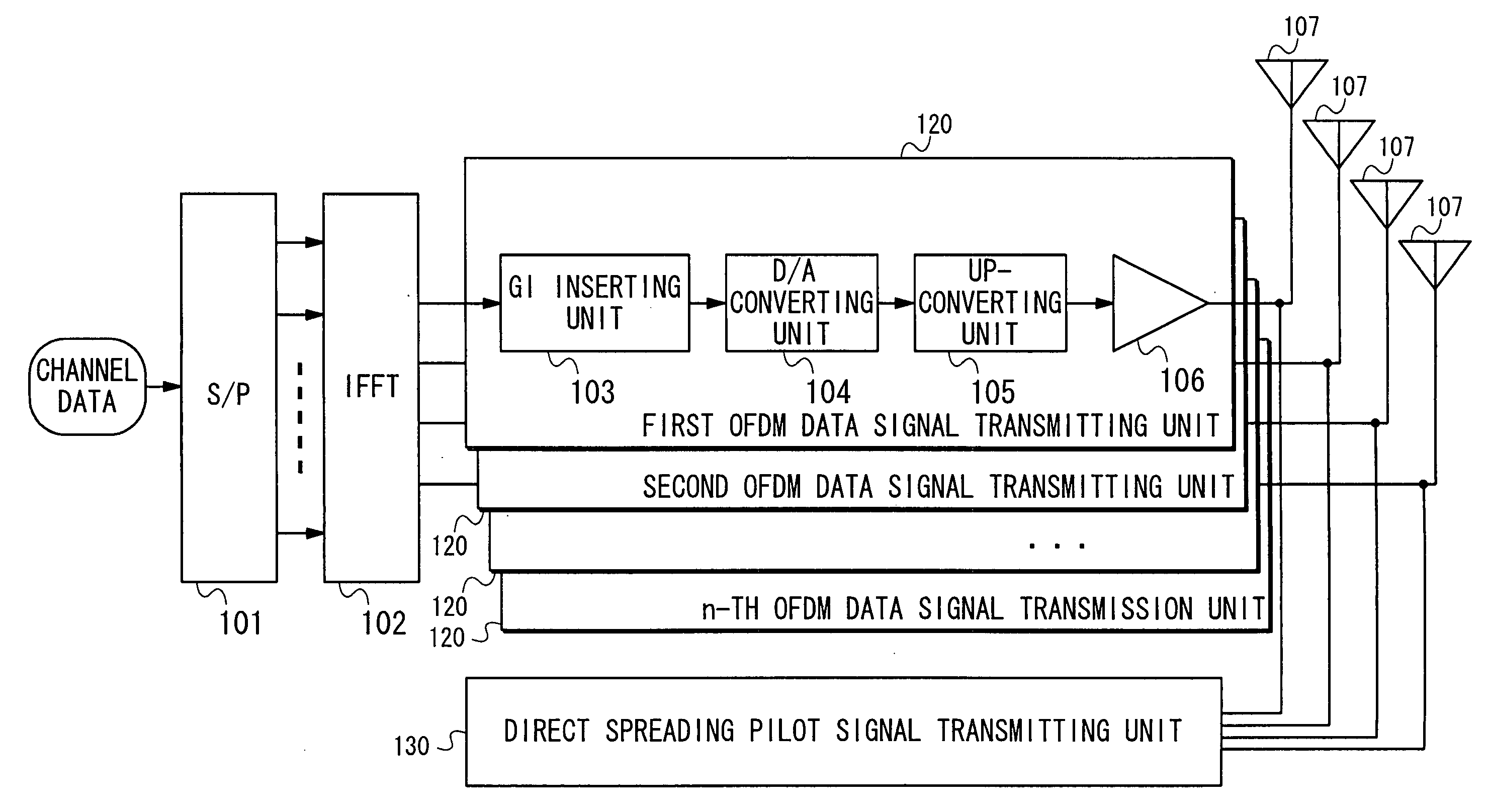
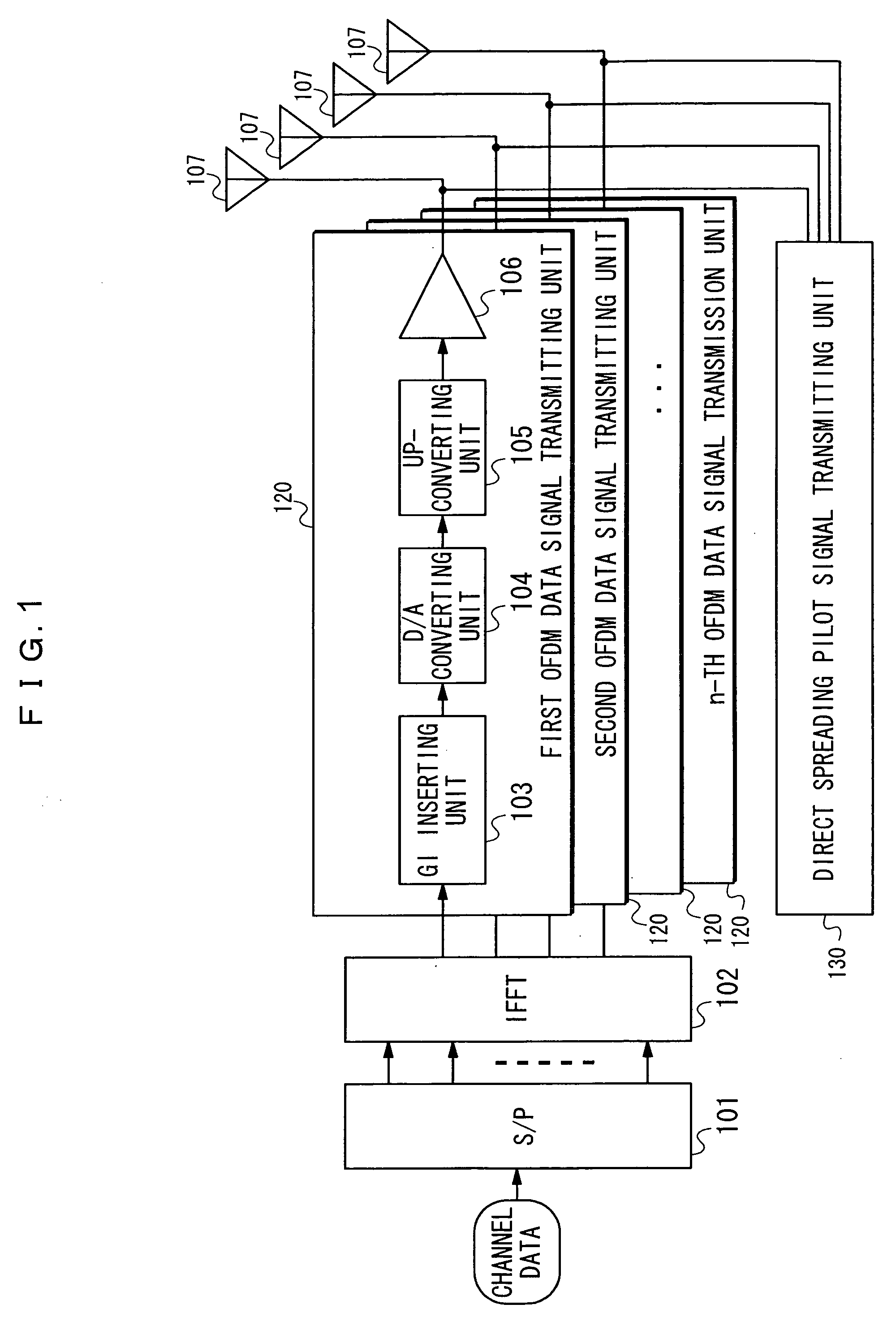
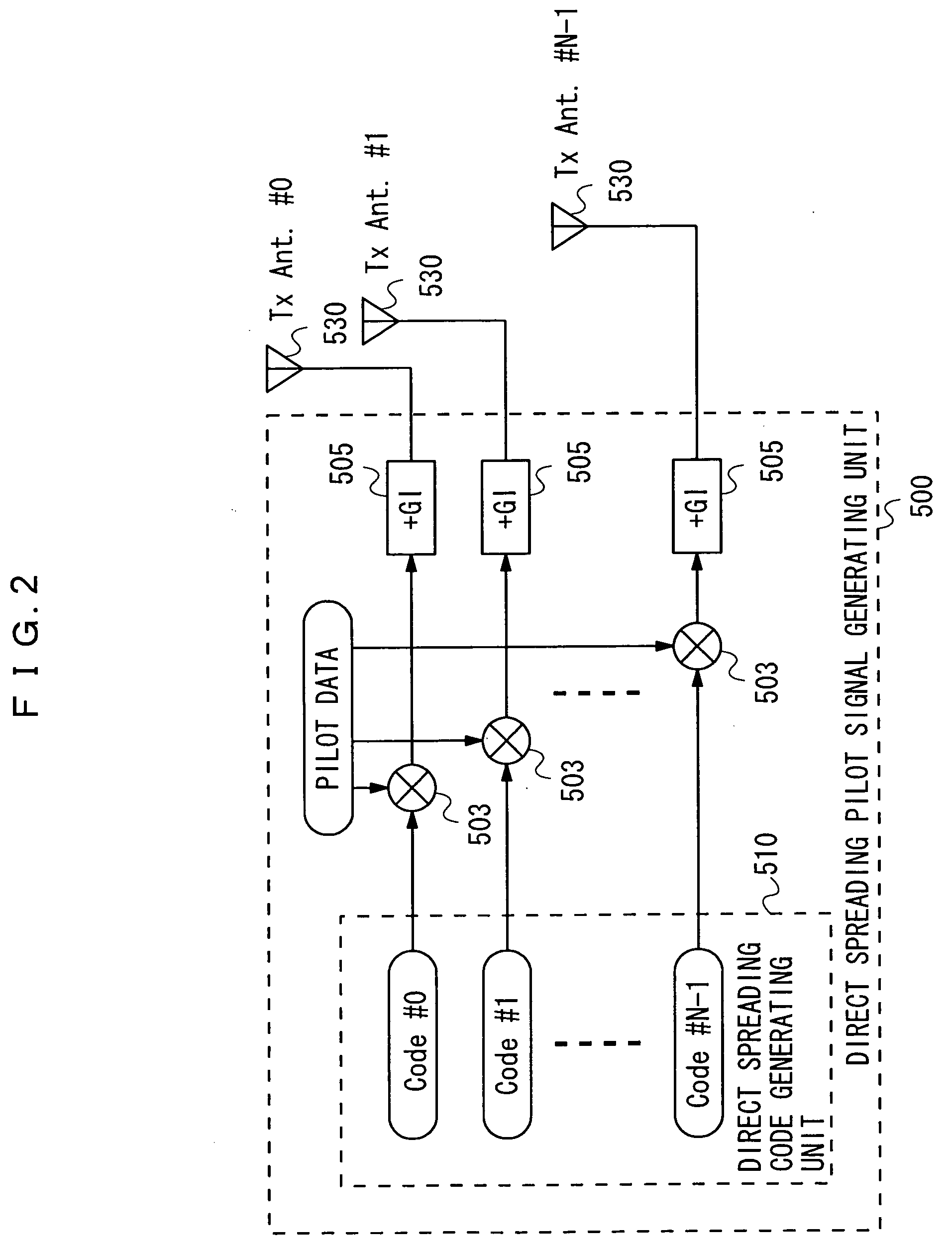
[0069]According to the first embodiment discussed so far, in the direct spreading pilot signal generating unit 500, the direct spreading code generating unit 510 generates the direct spreading code per transmitting antenna. The direct spreading pilot signals generated from the direct spreading codes are transmitted simultaneously from the respective transmitting antennas.
[0070]In the direct spreading pilot signal receiving unit 600, the matched filters 603 wait for the signals with the direct spreading codes generated per transmitting antenna by the direct spreading code generating unit 510. When the reception signals are inputted to the matched filters 603, the delay profiles for calculating the channel estimation values are obtained from the pilot signals.
[0071]according to the first embodiment, the pilot signals for every transmitting antenna can be organized in a state causing no interference between the pilot signals by spreading the pilot data with the direct spreading codes. This scheme enables the pilot signals (FIG. 20) per transmitting antenna, which have hitherto been transmitted by the time division, to be transmitted toward the receiver at the same transmission timing (FIG. 3). This operation makes it possible to reduce the transmitting time of the pilot signals, which have hitherto increased in proportion to the number of antennas, down to the pilot signal transmitting time for one operation.
[0072]Namely, according to the first embodiment, the pilot signal involves using the direct spreading pilot signal used for the CDMA method. To be specific, the direct spreading pilot signals using the individual direct spreading codes are transmitted from the respective antennas, thereby enabling the simultaneous transmissions of the pilot signals from the respective transmitting antennas, with the result that the pilot signal transmitting time can be reduced to a great degree.
Example
Second Embodiment
[0073]Next, a second embodiment of the present invention will be described. The second embodiment has the same configuration as of the first embodiment, and hence the description thereof will be focused mainly on a different point, while the explanations of the common points are omitted.
[0074]<>
[0075]FIG. 6 is a diagram showing a direct spreading pilot signal generating unit 700. The OFDM transmitter in the second embodiment has the same configuration of the MIMO-OFDM transmitter in the first embodiment except a point that the direct spreading pilot signal generating unit has a different configuration.
[0076]The direct spreading pilot signal generating unit 700 includes a direct spreading code generating unit 710, a multiplying unit 703 that multiplies, by the pilot data, the direct spreading code generated by the direct spreading code generating unit 710, a phase shifting unit 707 and a guard interval inserting unit 705. The direct spreading pilot signals generated by the direct spreading pilot signal generating unit 700 are transmitted from respective transmitting antennas 730.
[0077]The direct spreading code generating unit 710 generates only one direct spreading code (Code #0) for all of the transmitting antennas. The multiplying unit 703 multiplies, by the pilot data (the known signal), the direct spreading code generated by the direct spreading code generating unit 710.
[0078]The phase shifting unit 707 shifts a phase of the multiplied signal by n/N, and outputs the phase-shifted signal to the guard interval inserting unit 705. Herein, “n” represents a serial number of the transmitting antenna, and “N” represents a total number of the transmitting antennas. The phase shift is a process of replacing, in the case of shifting, e.g., a ¼ phase, a ¼ tailing portion of the signal and a ¾ leading portion of the signal with each other. FIG. 7 is a diagram showing an example of how the signal is shifted by the ¼ phase. One of the signals multiplied by the multiplying unit 703 is inputted, without being phase-shifted, to the guard interval inserting unit 705.
[0079]The guard interval inserting unit 705 attaches (inserts), as the guard interval, part of the tailing portion of the inputted signal, thereby organizing the direct spreading pilot signal. Further, a scheme of attaching none of the guard interval is also available.
[0080]The direct spreading pilot signals generated by the direct spreading pilot signal generating unit 700 are transmitted simultaneously from the respective transmitting antennas 730.
[0081]The transmission timing of the pilot signal in the second embodiment is the same of the transmission timing of the pilot signal in the first embodiment (FIG. 3). The respective transmitting antennas are capable of reducing the transmitting time of the pilot signals because of simultaneously transmitting the direct spreading pilot signals.
[0082]<>
[0083]FIG. 8 is a diagram showing an example of a configuration for receiving the direct spreading pilot signals based on the same direct spreading code from the respective antennas. The MIMO-OFDM receiver in the second embodiment has the same configuration as of the OFDM receiver in the first embodiment except a point that the direct spreading pilot signal receiving unit has a different configuration.
[0084]A direct spreading pilot signal receiving unit 800 includes a guard interval removing unit 805 and a matched filter 803 corresponding to the direct spreading code.
[0085]The guard interval removing unit 805 removes the guard intervals from the signals received by receiving antennas 830, and outputs the GI-removed signals to the matched filter 803. The matched filter 803 waits for the signals with the direct spreading code generated by the direct spreading code generating unit 710. When the reception signals are inputted to the matched filter 803, the delay profile of each transmitting antenna is acquired. All of the transmitters employ the single direct spreading code, and the delay profiles of all of the transmitters are acquired with the output of the single matched filter.
[0086]FIG. 9 is a diagram showing the delay profile obtained by the matched filter. Generally, a width of the delay profile is well small as compared with a length of the OFDM symbol, and hence, as illustrated in FIG. 9, the delay profiles of the transmitting antennas are acquired in the form of being spaced in time from each other. The delay profiles of the individual transmitting antennas can be easily separated according to every transmitting antenna. The channel estimation values of the transmitting antennas can be calculated by use of the delay profiles of these individual transmitting antennas.
Operation and Effect in Second Embodiment
[0087]According to the second embodiment discussed so far, in the direct spreading pilot signal generating unit 700, the direct spreading code generating unit 710 generates the direct spreading code. Generated also is the direct spreading pilot signal given the phase shift of which quantity is different for every transmitting antenna. This direct spreading pilot signal is transmitted from each transmitting antenna.
[0088]In the direct spreading pilot signal receiving unit 800, the matched filter 803 waits for the signals with the direct spreading code generated by the direct spreading code generating unit 710. When the reception signals are inputted to the matched filter 803, the delay profiles of all of the transmitting antennas are obtained.
[0089]According to the second embodiment, the transmitting time of the pilot signals can be reduced. Further, only one matched filter may be sufficient by utilizing the same direct spreading code for all of the transmitting antennas, and hence the device can be simplified.
Example
Third Embodiment
[0090]Next, a third embodiment of the present invention will be described. The third embodiment has the same configuration as of the first embodiment, and hence the description thereof will be focused mainly on a different point, while the explanations of the common points are omitted.
[0091]<>
[0092]FIG. 10 is a diagram showing a direct spreading pilot signal generating unit 900. The OFDM transmitter in the third embodiment has the same configuration of the MIMO-OFDM transmitter in the first embodiment except a point that the direct spreading pilot signal generating unit has a different configuration. The direct spreading pilot signal generating unit 900 includes a direct spreading code generating unit 910, a multiplying unit 903 that multiplies, by the pilot data, the direct spreading code generated by the direct spreading code generating unit 910, a phase shifting unit 907 and a guard interval inserting unit 905. The direct spreading pilot signals generated by the direct spreading pilot signal generating unit 900 are transmitted from respective transmitting antennas 930.
[0093]The direct spreading code generating unit 910 generates only one direct spreading code for all of the transmitting antennas. Herein, the direct spreading code involves using a code such as an M-sequence (maximum length sequence) code exhibiting a good autocorrelation (the M-sequence code is applied in the third embodiment). FIG. 12 is a diagram showing a characteristic of the autocorrelation of the M-sequence code having a code length 127. In the case of taking the autocorrelation of the code length 127, the code length comes to 127 when perfectly in phase and becomes −1 when the phase is shifted.
[0094]The phase shifting unit 907 shifts a phase of the multiplied signal by n/N, and outputs the phase-shifted signal to the guard interval inserting unit 905. Herein, “n” represents a serial number of the transmitting antenna, and “N” represents a total number of the transmitting antennas. The phase shift is the same process as in the second embodiment. One of the signals multiplied by the multiplying unit 903 is inputted, without being phase-shifted, to the guard interval inserting unit 905.
[0095]The guard interval inserting unit 905 attaches (inserts), as the guard interval, part of the tailing portion of the inputted signal, thereby organizing the direct spreading pilot signal. Further, the scheme of attaching none of the guard interval is also available.
[0096]The direct spreading pilot signals generated by the direct spreading pilot signal generating unit 900 are transmitted simultaneously from the respective transmitting antennas 930.
[0097]The transmission timing of the pilot signal in the third embodiment is the same of the transmission timing of the pilot signal in the first embodiment. The respective transmitting antennas are capable of reducing the transmitting time of the pilot signals because of simultaneously transmitting the direct spreading pilot signals.
[0098]<>
[0099]FIG. 11 is a diagram showing an example of a configuration for receiving the direct spreading pilot signals based on the same direct spreading code from the respective antennas. The MIMO-OFDM receiver in the third embodiment has the same configuration as of the OFDM receiver in the first embodiment except a point that the direct spreading pilot signal receiving unit has a different configuration.
[0100]A direct spreading pilot signal receiving unit 1000 includes a guard interval removing unit 1005 and a matched filter 1003 corresponding to the direct spreading code (M-sequence code).
[0101]The guard interval removing unit 1005 removes the guard intervals from the signals received by receiving antennas 1030, and outputs the GI-removed signals to the matched filter 1003. The matched filter 1003 waits for the signals with the direct spreading code (M-sequence code) generated by the direct spreading code generating unit 910. When the reception signals are inputted to the matched filter 1003, the delay profile of each transmitting antenna is acquired. All of the transmitters employ the single direct spreading code (M-sequence code), and the delay profiles of all of the transmitters are acquired with the output of the single matched filter.
[0102]The delay profile obtained by the matched filter 1003 is the same as the delay profile (FIG. 9) obtained by the matched filter 803 in the second embodiment. The channel estimation value of each transmitting antenna can be calculated from the delay profile of each transmitting antenna.
Operation and Effect in Third Embodiment
[0103]According to the embodiment discussed so far, in the direct spreading pilot signal generating unit 900, the direct spreading code generating unit 910 generates the direct spreading code (M-sequence code). Generated also is the direct spreading pilot signal that is phase-shifted with a quantity different for every transmitting antenna. The direct spreading pilot signals are transmitted simultaneously from the respective transmitting antennas.
[0104]In the direct spreading pilot signal receiving unit 1000, the matched filter 1003 waits for the signals with the direct spreading code (M-sequence code) generated by the direct spreading code generating unit 910. When the reception signals are inputted to the matched filter 1003, the delay profiles of all of the transmitting antennas are obtained.
[0105]According to the third embodiment, the transmitting time of the pilot signals can be reduced. Moreover, all of the transmitting antennas use the same direct spreading code, and hence only one matched filter may be sufficient, whereby the device can be simplified. Further, the M-sequence code has the preferable autocorrelation characteristic, thereby restraining the interference between the signals and improving accuracy of the delay profile obtained by the matched filter 1003.
PUM


Description & Claims & Application Information
We can also present the details of the Description, Claims and Application information to help users get a comprehensive understanding of the technical details of the patent, such as background art, summary of invention, brief description of drawings, description of embodiments, and other original content. On the other hand, users can also determine the specific scope of protection of the technology through the list of claims; as well as understand the changes in the life cycle of the technology with the presentation of the patent timeline. Login to view more.
Similar technology patents
Incremental map generation, refinement and extension with GPS traces
Owner:TOMTOM GLOBAL CONTENT
Image reading apparatus
Owner:FUJIFILM BUSINESS INNOVATION CORP
Method predicting view synthesis in multi-view video coding and method for constituting merge candidate list by using same
Owner:LG ELECTRONICS INC
Method and device for updating data in distributed storage system
Owner:SHANDA INTERACTIVE ENTERTAINMENT
Pre-ordering based on location of a customer
Owner:BANK OF AMERICA CORP
Classification and recommendation of technical efficacy words
- reduce time
- improve efficiency
Multi-component vascular device
Owner:ST JUDE MEDICAL CARDIOLOGY DIV
System and method for adaptive medical decision support
Owner:ONCOMPASS GMBH
Video coding methods and apparatuses
Owner:MICROSOFT TECH LICENSING LLC
Dynamic player groups for interest management in multi-character virtual environments
Owner:MICROSOFT TECH LICENSING LLC
Method and apparatus for controlling a selectable voltage audio power output stage
Owner:CIRRUS LOGIC INC
Wireless power transmitter and power transmission method thereof
Owner:LG INNOTEK CO LTD