[0012]An object of the invention is, in an image forming apparatus utilizing a concurrently transferring and fixing method, to provide an image forming apparatus which has a high efficiency of transferring a toner image from an intermediate transfer member to a transferring and fixing member, is capable of stably forming a high-definition image, and of further reducing its power consumption, even when forming an image at high speed, by applying a comparatively simplified configuration with no necessity of upsizing.
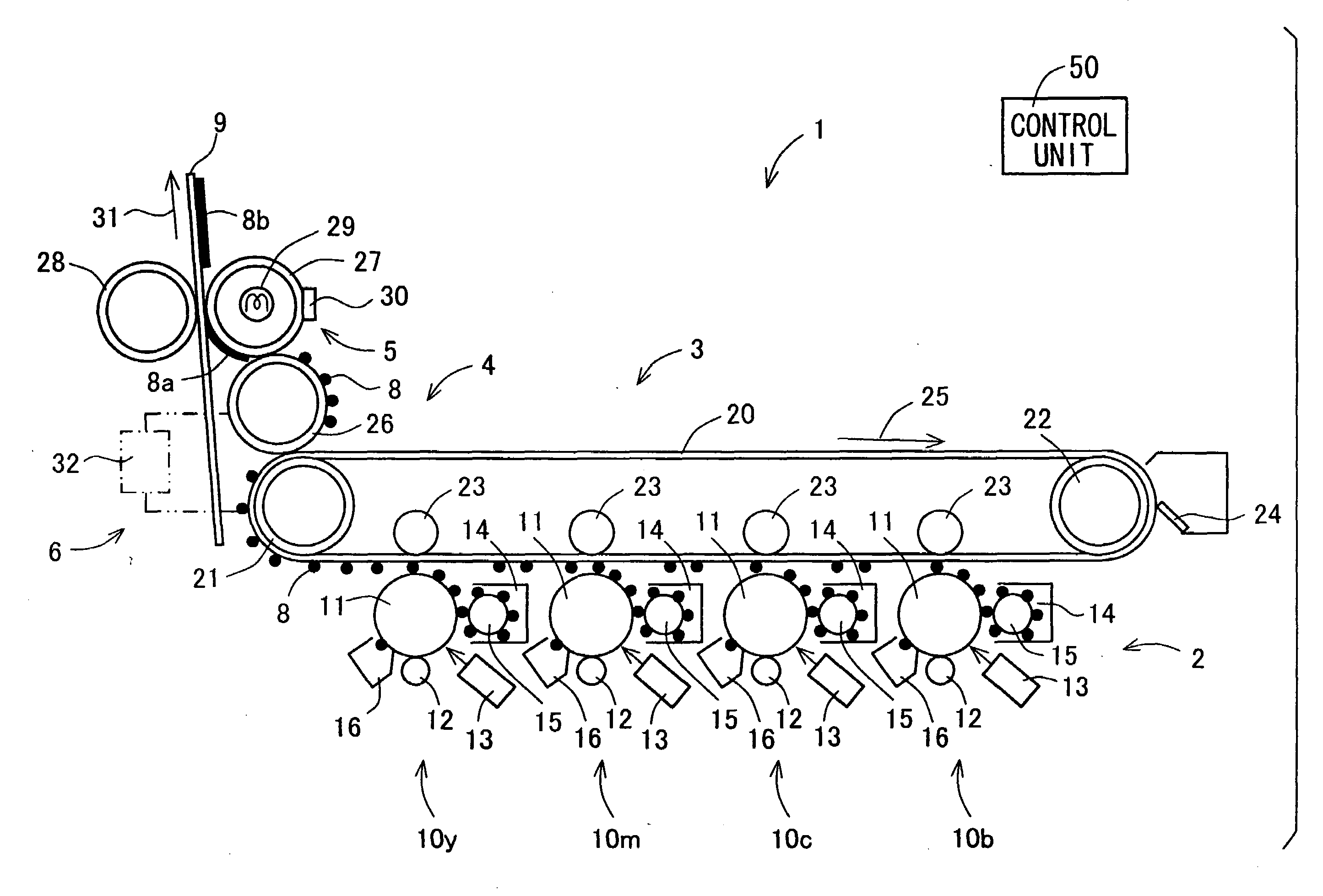
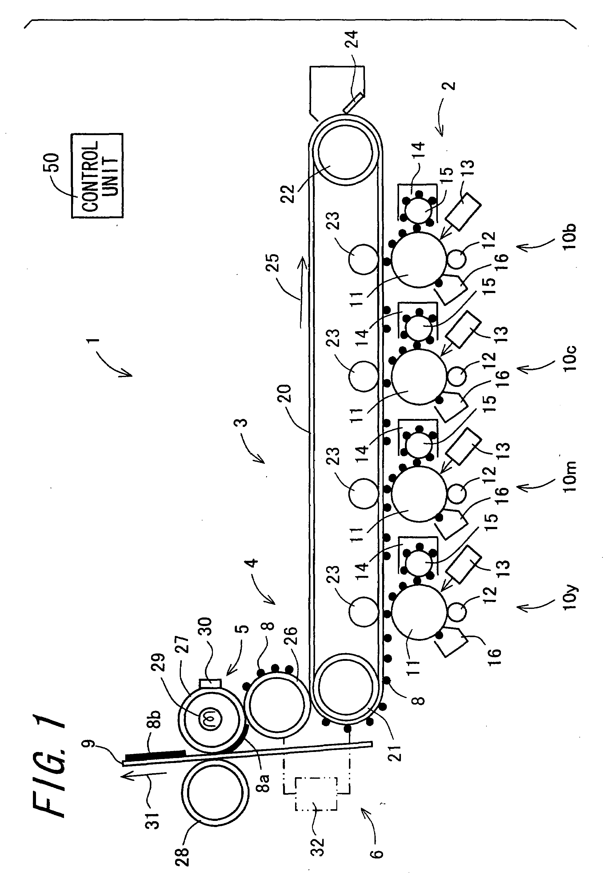
[0018]According to the invention, there is provided the image forming apparatus comprising the toner image bearing section including the photoreceptor, the first intermediate transfer section, the second intermediate transfer section, and the transferring and fixing section including the toner image heating section. In the image forming apparatus of the invention, by arranging the second intermediate transfer section between the first intermediate transfer section and the transferring and fixing section including the toner image heating section, the second intermediate transfer section functions as a heat buffering member, and heat generated from the toner image heating section of the transferring and fixing section is transferred to the photoreceptor of the toner image bearing section and the like, thereby preventing a temperature of the photoreceptor from increasing to cause heat deterioration of the photoreceptor. Therefore, a need for cooling by force the first intermediate transfer section for receiving a transfer of the toner image from the photoreceptor is eliminated, thereby preventing an increase in its power consumption in association with the forced cooling. In addition, an amount of heat conduction is decreased, resulting in a decrease in its power consumption. Therefore, prevention of the heat deterioration of the photoreceptor, and reduction of its power consumption particularly in the transferring and fixing section are achieved at the same time. In addition, the toner image is transferred under heat and pressure from the first intermediate transfer section to the second intermediate transfer section, and then from the second intermediate transfer section to the transferring and fixing section. The toner image is transferred under heat and pressure by forming a film of the toner image. As described in the invention, by forming a film of the toner image two times, a high-gloss and high-definition image is formed. Further, the second intermediate transfer section is configured with members such as a roller, a belt, and the like, each having a comparatively small size, thereby providing excellent effects as described above with no upsizing of the apparatus.
[0020]According to the invention, by further comprising the
heat control section for controlling heating of the transferring and fixing section by the toner image heating section, and by controlling the heating by the toner image heating section so that the surface temperature of the transferring and fixing section reaches or exceeds the
glass transition temperature of the toner, the transferring and fixing section, the second intermediate transfer section, and the first intermediate transfer section each has the surface temperature decreased in this order. Accordingly, the toner image is efficiently transferred. That is, in a first intermediate transfer nip area which is formed by the first intermediate transfer section and the second intermediate transfer section, and in a second intermediate transfer nip area which is formed by the second intermediate transfer section and the transferring and fixing section, a
temperature gradient is produced so that the surface temperature of a side receiving a transfer of the toner image becomes higher. Accordingly, when the toner image passes through each nip area, the surface of the toner image facing the surface of a side receiving the transfer has a higher temperature, and thus the toner image is transferred to a side having the higher surface temperature. Therefore, transfer capability of the toner image is improved. When the surface temperature of the transferring and fixing section is controlled to the
glass transition temperature of the toner or a temperature higher than the
glass transition temperature thereof, the heat functions so as to support the transfer of the toner image, thus providing an
advantage, for example, in a case in which its transfer capability is decreased due to an increased number of the transfer.
[0022]According to the invention, by arranging the
voltage applying section for applying a
voltage to an area between the first intermediate transfer section and the second intermediate transfer section, in addition to the transfer of the toner
image based on a heat gradient, the transfer of a toner using an effect of an electrical field becomes possible, when the toner image is transferred from the first intermediate transfer section to the second intermediate transfer section. Therefore, in particular, when two or more
layers of the toner image having different colors are superimposed to transfer a multiple color toner image having a large amount of toner attachment per unit area, a multiplier effect of the heat gradient and the effect of the electrical field further improves its transfer capability, providing an image having excellent color reproducibility.
[0024]According to the invention, by arranging the fixer applying section for applying the fixer having an effect that the toner constituting the toner image is softened, and by applying the fixer to the toner image borne by the transferring and fixing section and / or to the transferring and fixing section, a
heating temperature of the transferring and fixing section is decreased compared with a case in which the fixer applying section is not provided. As a result, reduction of a warm-up period that is a time period that the surface temperature of the transferring and fixing section takes to reach a setting temperature, reduction of its power consumption, and the like are achieved. In addition, the decreased heat temperature of the transferring and fixing section further reduces thermal influence on the photoreceptor and the like.

