Rotor blade for a wind turbine

Inactive Publication Date: 2007-11-01
GENERAL ELECTRIC CO
View PDF11 Cites 38 Cited by
  • Summary
  • Abstract
  • Description
  • Claims
  • Application Information

AI Technical Summary

Benefits of technology

[0009] According to a further embodiment of the present invention, the diameter of radial bores proximate the hub end of the rotor blade is smaller than the diameter of radial bores distant from the hub end of the rotor blade. Thus, the amount of root laminate between a radial bor

Problems solved by technology

What makes the design of the blade connection to the rotor hub a difficult task is the load transfer from the fiber composite structure of the rotor blade into the metal structure of the rotor hub.
Such a load transfer is difficult in principle due to the substantially different properties of the mat

Method used


Image

  • Rotor blade for a wind turbine
  • Rotor blade for a wind turbine
  • Rotor blade for a wind turbine

Examples


Embodiment Construction

[0021] Reference will now be made in detail to the various embodiments of the invention, one or more examples of which are illustrated in the figures. Each example is provided by way of explanation of the invention, and is not meant as a limitation of the invention. For example, features illustrated or described as part of one embodiment can be used on or in conjunction with other embodiments to yield yet a further embodiment. It is intended that the present invention includes such modifications and variations.

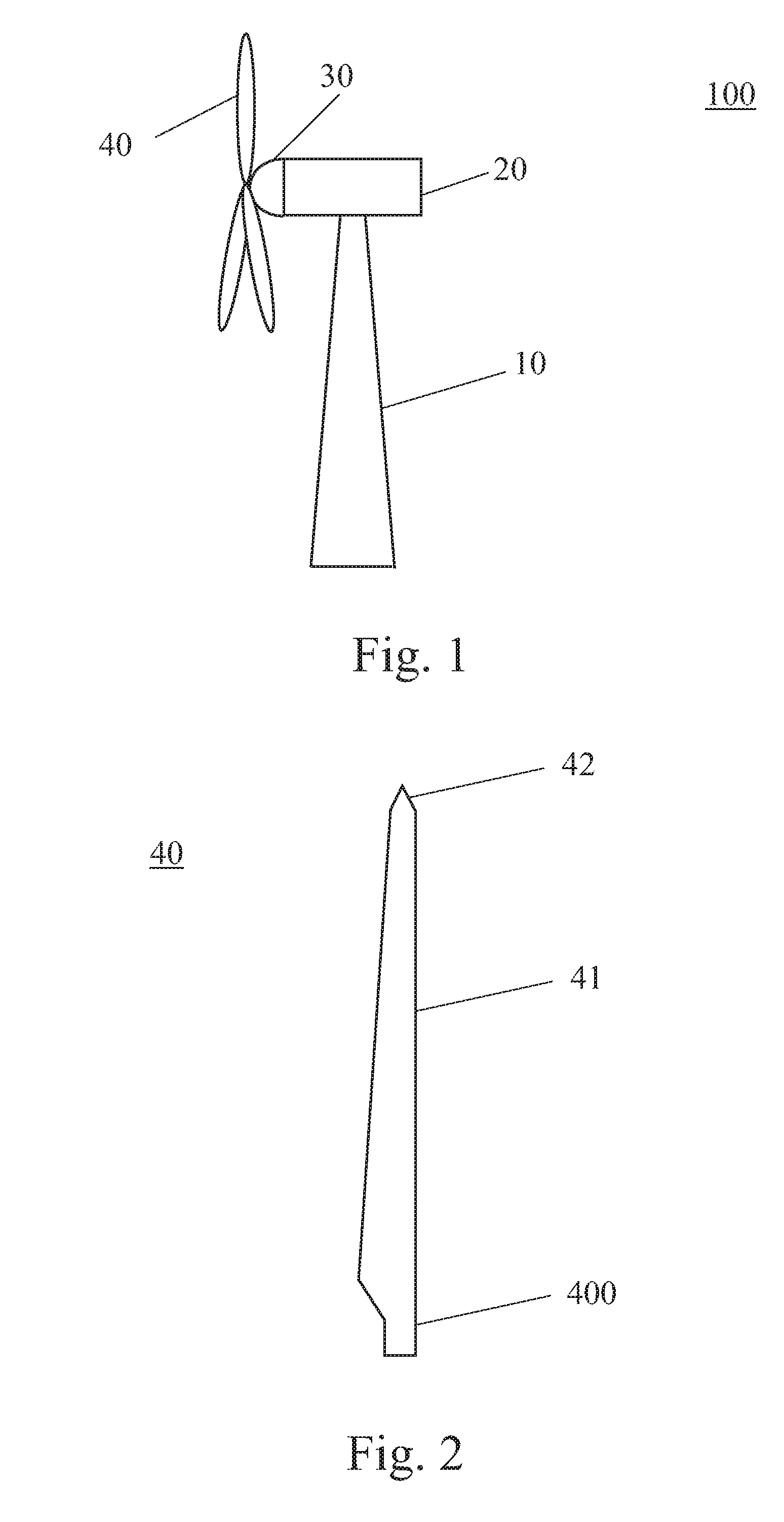
[0022]FIG. 1 is a schematic view of a conventional wind turbine 100. The wind turbine 100 includes a tower 10 to which a machine nacelle 20 is mounted at its top end.

[0023] A hub 30 bearing three rotor blades 40 is mounted to a lateral end of the machine nacelle 20.

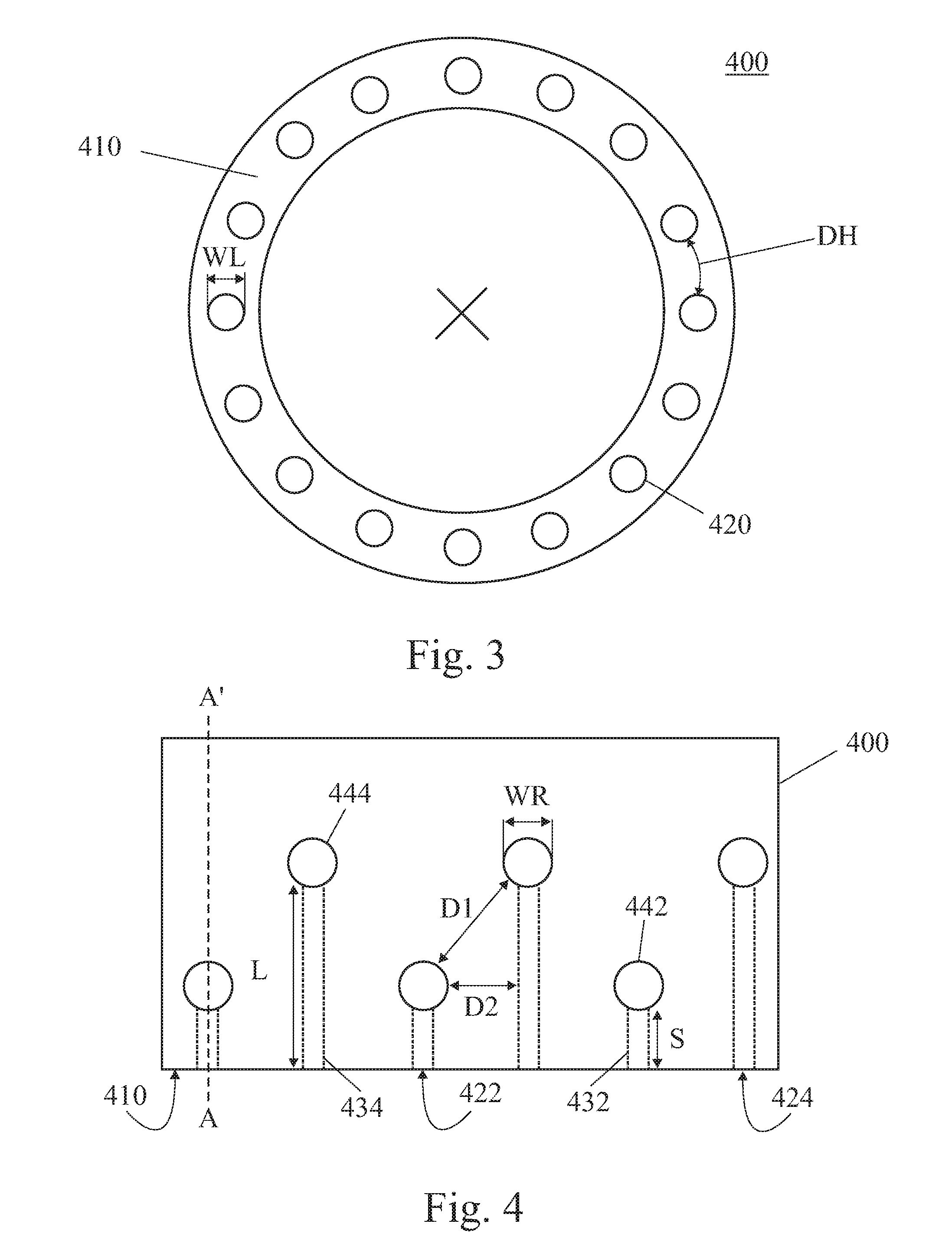
[0024] The basic configuration of a rotor blade 40 is shown in FIG. 2. Therein, the rotor blade 40 includes a root section 400 which serves for mounting rotor blade 40 to hub 30. Opposite to root section 400, the...


PUM


Abstract

A rotor blade for a wind turbine is provided, wherein the rotor blade has radial bores in a wall of a blade root portion, the radial bores being staggered in a longitudinal direction of the rotor blade, and longitudinal bores in the wall of the blade root portion, wherein each of the longitudinal bores extends from a blade flange to a corresponding radial bore.

Description

FIELD OF THE INVENTION [0001] The present invention relates to a rotor blade for a wind turbine and, especially, to the configuration of the root section of such a rotor blade. Furthermore, the invention relates to a wind turbine having such a rotor blade. BACKGROUND OF THE INVENTION [0002] Apart from the aerodynamic design of a wind turbine rotor blade, the quality and weight of the rotor blades are essentially determined by the design of the blade connection to the rotor hub, i.e. the blade root section. What makes the design of the blade connection to the rotor hub a difficult task is the load transfer from the fiber composite structure of the rotor blade into the metal structure of the rotor hub. Such a load transfer is difficult in principle due to the substantially different properties of the materials involved. A known technique for attaching the rotor blades to the hub is to form T-bolt or cross-bolt connections between the blade root and the hub. [0003] However, the rotor l...

Claims


Application Information

Patent Timeline
IPC IPC(8): B64C27/50
CPCF03D1/0658Y02E10/721F05B2260/301F05B2250/34Y02E10/72
Inventor DOORENSPLEET, FLORIANARELT, RAINEREYB, ENNO
Owner GENERAL ELECTRIC CO
Why Eureka
Try Eureka