Foam Buffing Pad with Random or Strategically Placed Collapsed Cell Structures

a cell structure and foam buffing technology, applied in the direction of grinding devices, carpet cleaners, manufacturing tools, etc., can solve the problems of clogging the hook-and-loop fastening system, affecting the effect of the pad, and preventing the penetration of moisture into the pad attachment fa

Active Publication Date: 2007-11-01
LAKE COUNTRY MFG
View PDF11 Cites 15 Cited by
  • Summary
  • Abstract
  • Description
  • Claims
  • Application Information

AI Technical Summary

Benefits of technology

[0006]Adding random or specific depressions of partially collapsed cell structures to the operating face of the pad has several advantages over conventional, well known foam pads, namely, depressions of collapsed cell structures will slow down the rate of polish or compound absorption, thereby increasing the effectiveness of the polish or compound, and at the same time, saving the end user money by not requiring as much polish to perform the task; depressions of collapsed cell structures will break surface tension that constant full faced pads present, lessening the frequency of pad skipping; depressions of collapsed cell structures provide areas for debris commonly found on working surface to collect, thereby presenting a foam pad that will scratch less; depressions of collapsed cell structures, with less surface-to-surface contact, will reduce surface friction, thereby creating less heat which can damage the working surface; depressions of collapsed cell structures can aid in advertising by imprinting a client's logo or name in the surface of pad; and, depressions of collapsed cell structures are not limited to any shape, size or pattern. Specific shapes, depths and patterns will change the performance of the pad.
[0008]The method of the present invention can also be applied to form an impervious surface of fully collapsed cell structures on the rear attachment face of the pad to prevent or substantially preclude the migration of moisture or other carrier liquid all the way through the pad from the front working face.

Problems solved by technology

This absorption creates a less effective working surface because the polish, which has abrasives in it, is not on the surface where it needs to be to accomplish the finishing task most efficiently.
Here the compound can collect and, in addition to being messy, can clog the hook-and-loop fastening systems by which the pad is attached to the rotary or orbital driving device.
It has been found that prior art pad mounting mechanisms do not adequately inhibit the penetration of moisture to the pad attachment face and the attachment device being used.

Method used


Image

  • Foam Buffing Pad with Random or Strategically Placed Collapsed Cell Structures
  • Foam Buffing Pad with Random or Strategically Placed Collapsed Cell Structures
  • Foam Buffing Pad with Random or Strategically Placed Collapsed Cell Structures

Examples


Embodiment Construction

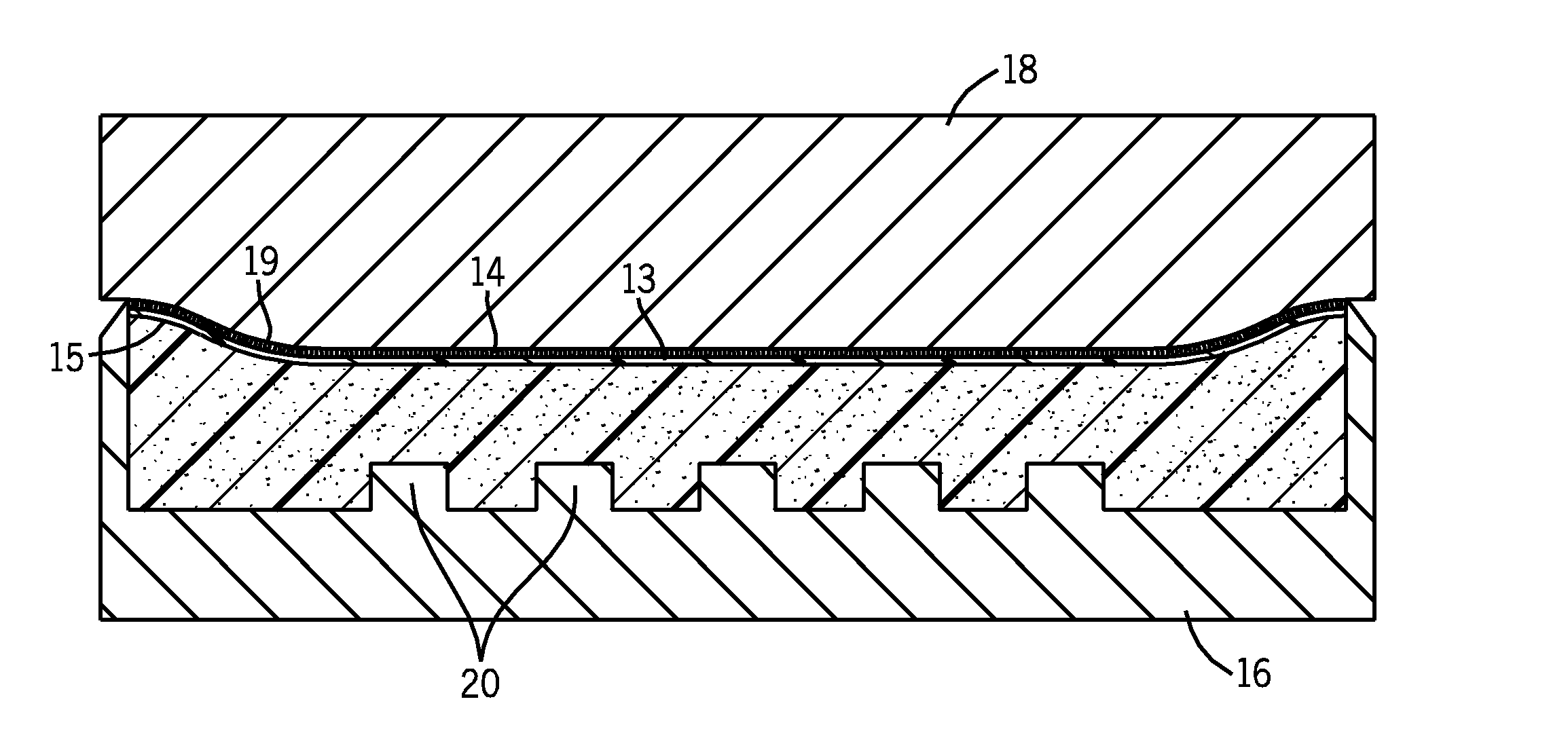
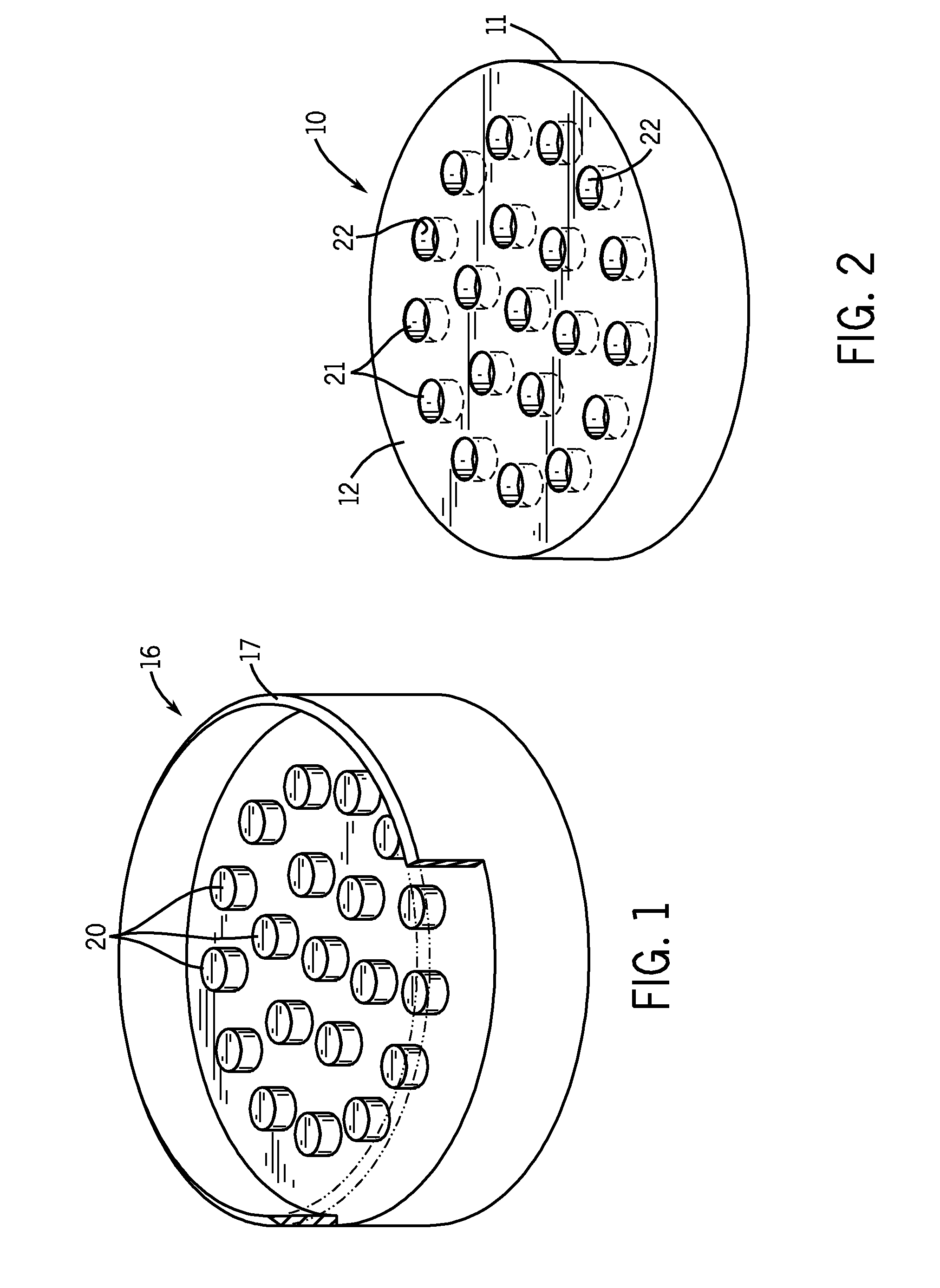
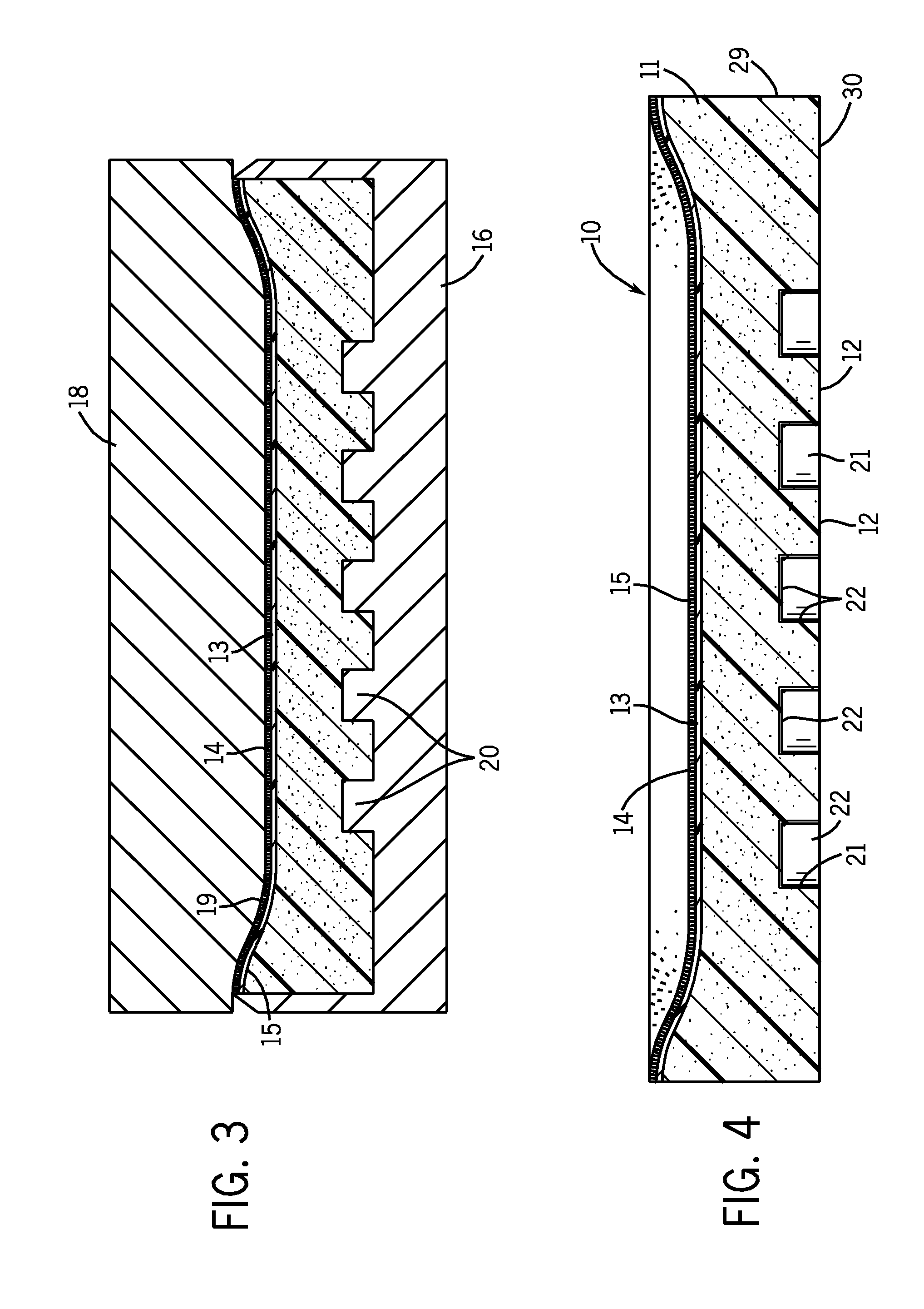
[0024]Referring initially to FIGS. 2 and 4, a buffing, polishing or finishing pad 10 is formed from a sheet of polyurethane foam. As is generally well known in the art, the pad 10 is a composite of a foam body 11, having a front operating face 12 and a rear attachment face 13 comprising a sheet of loop scrim 14 attached by heat sealing to the rear face 13 by an intermediate sheet of polyethylene 15.

[0025]The die from which the pad is formed includes a front die half 16 (FIG. 1) having a recessed interior surrounded by a peripheral knife edge 17 to cut the foam body from a sheet of polyurethane foam. A rear die half 18 may include a slightly convex protruding surface 19 that forms a shallow dished rear attachment face 13 on the pad 10. The attachment face could also be flat or planar. The loop scrim 14 on the rear face 13 is intended to be attached to a hook scrim sheet (not shown) comprising the other half of a conventional hook and loop fastening system. The hook scrim sheet is typ...


PUM

PropertyMeasurementUnit
temperatureaaaaaaaaaa
surface areaaaaaaaaaaa

Abstract

Selected surfaces of a cellular polymeric foam surface finishing pad are heated to cause the surface cells to partially collapse or to fully collapse and glaze over. The selected surfaces may be the planar pad faces or may be formed in one or more depressions formed in the planar faces. The areas of partially collapsed cell structures in the operating face of the pad provide a slow down in the rate of polish or compound absorption, increasing the effectiveness of the finishing process. The fully collapsed cell glazed surface on the rear attachment face of the pad prevents the migration of moisture through the pad to the pad attachment mechanism.

Description

CROSS REFERENCE TO RELATED APPLICATIONS[0001]This application claims priority from U.S. Provisional Application Ser. No. 60 / 796,457, filed May 1, 2006.BACKGROUND OF THE INVENTION[0002]Foam buffing and finishing pads are typically made from a polymeric foam material, such as open cell polyurethane foam.[0003]Conventional foam pads have tendency to absorb the water or petroleum-based polish or compound that is used in conjunction with the foam pad to accomplish the task of defect removal from painted and non-painted surfaces. This absorption creates a less effective working surface because the polish, which has abrasives in it, is not on the surface where it needs to be to accomplish the finishing task most efficiently.[0004]Migrating water or petroleum-based polish or compound can penetrate the entire buffing pad and reach all the way to the rear attachment face. Here the compound can collect and, in addition to being messy, can clog the hook-and-loop fastening systems by which the p...

Claims


Application Information

Patent Timeline
Patent Type & Authority Applications(United States)
IPC IPC(8): B24D17/00B24D99/00
CPCB24D3/26B24D18/0009B24D13/147
Inventor MCLAIN, SCOTT S.
Owner LAKE COUNTRY MFG
Why Eureka
Try Eureka