Mr apparatus and operating method to set RF transmit parameters

a magnetic resonance system and transmit parameter technology, applied in the field of magnetic resonance system control, can solve the problems of non-homogeneous penetration behavior of radio-frequency pulses in conductive and dielectric media, distortion of measurement, and inability to see pathological structures, and achieve good set of rf transmit parameters

Active Publication Date: 2007-11-01
SIEMENS HEALTHCARE GMBH
View PDF9 Cites 24 Cited by
  • Summary
  • Abstract
  • Description
  • Claims
  • Application Information

AI Technical Summary

Benefits of technology

[0011] An object of the present invention is to provide a possibility for determining in a rapid manner, i.e. in ...

Problems solved by technology

Spatial fluctuations in the field strength of the exciting B1 field therefore lead to undesired variations in the magnetic resonance signal received, and these variations can distort the measurement result.
Disadvantageously, however, it is precisely where magnetic field strengths are high—which is necessarily the case because of the main field B0 that is needed in a nuclear spin tomograph—that radio-frequency pulses display non-homogeneous penetration behavior in conductive and dielectric media such as, e.g., body tissue.
Contrast and brightness of the recorde...

Method used


Image

  • Mr apparatus and operating method to set RF transmit parameters
  • Mr apparatus and operating method to set RF transmit parameters
  • Mr apparatus and operating method to set RF transmit parameters

Examples


Embodiment Construction

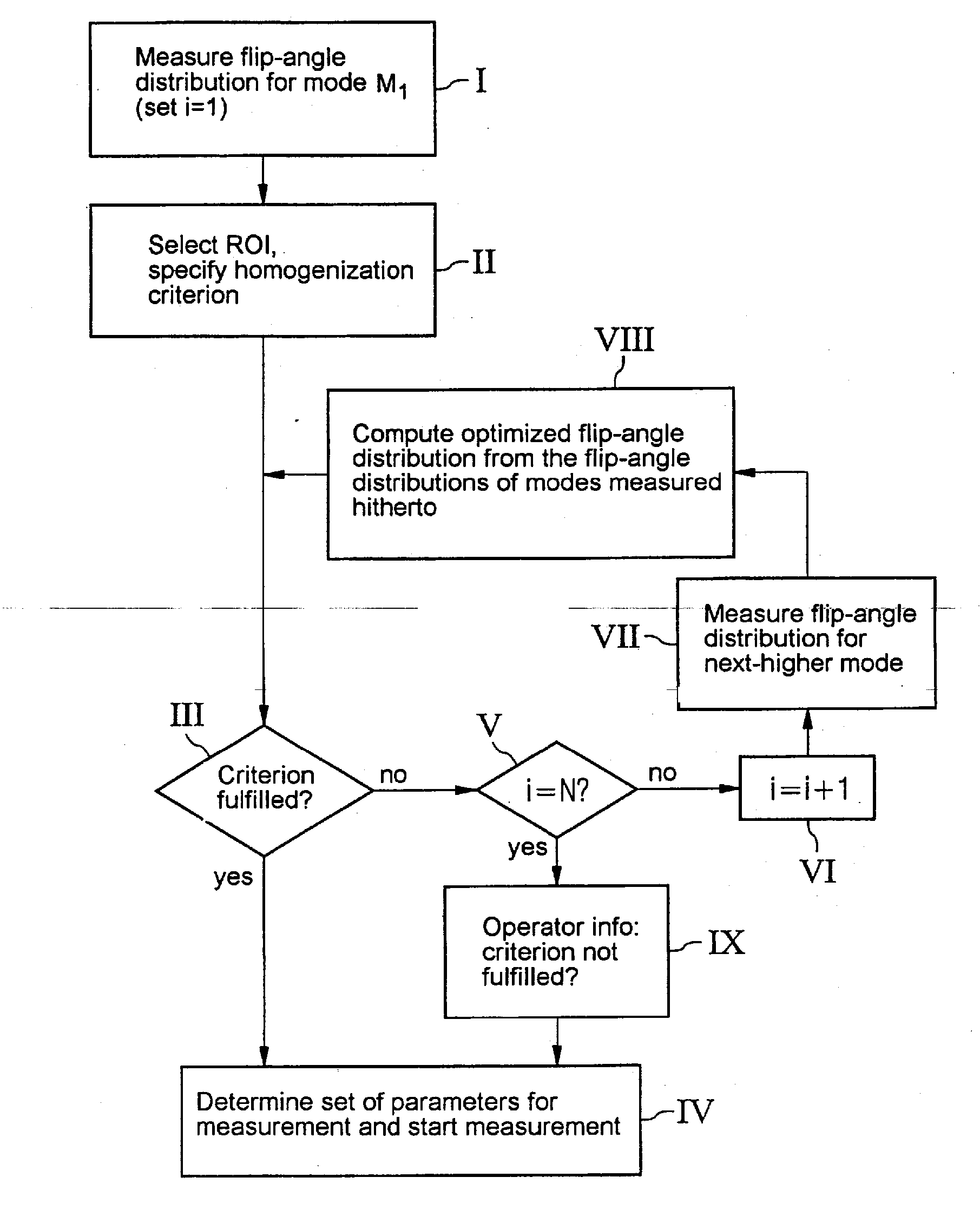
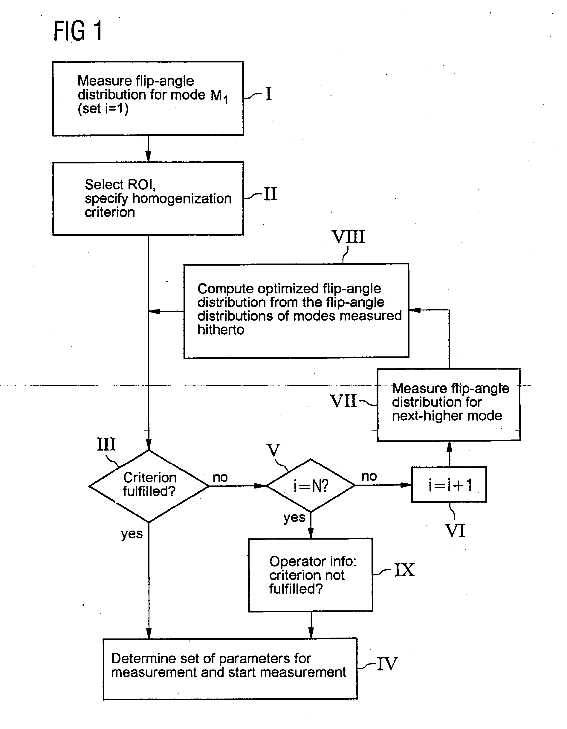
[0040] A possible measurement, evaluation and computation process according to a variant of the inventive method is shown in FIG. 1 with a flowchart.

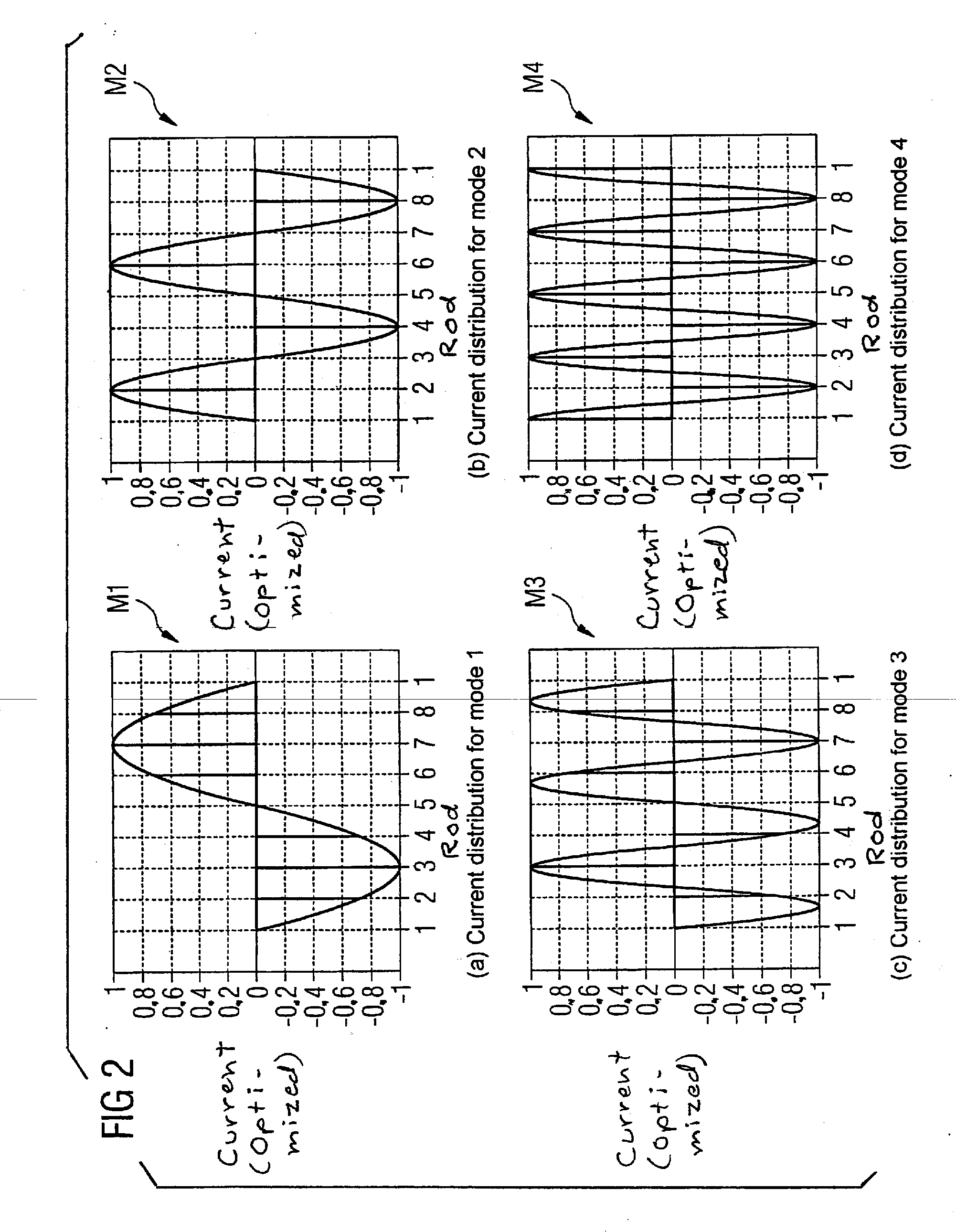
[0041] In step 1, firstly a flip-angle distribution inside the region of interest is measured for the first transmit mode M1. For a birdcage antenna with eight rods, the current distribution is represented for this first mode M1 (diagram a) of FIG. 2). The current is plotted here (in relative units) over the individual rods 1 to 8. As can clearly be seen, in the first mode M1, the basic mode, a current distribution is plotted such that a current period is distributed precisely between the eight rods. That is, in a phase in which—as shown in FIG. 2—no current is being applied to the first and the fifth rods, the maximum current is being applied to the third and seventh rod, the numbering of the rods being arbitrary.

[0042] With such a resonator with N=8 rods, in principle N=8 different, linearly independent transmit modes can be generat...


PUM


Abstract

In al magnetic resonance system and a method for operating the magnetic resonance system to set RF transmit parameters for a radio-frequency antenna that is excitable in a number of different, linearly independent transmit modes, the transmit antenna is successively caused to be excited in the different transmit modes, and, for each transmit mode in which the radio-frequency antenna is excited, a measured value distribution representing the radio-frequency field produced by the antenna in a defined volume area is determined. The homogeneity of the measured value distribution is evaluated with respect to a defined evaluation criterion and, if the evaluation criterion is satisfied, an optimized radio-frequency field distribution is determined from a combination of the measured value distributions up to that time. If the evaluation criterion is not fulfilled, the radio-frequency antenna is excited with a further transmit mode, and the procedure is repeated.

Description

BACKGROUND OF THE INVENTION [0001] 1. Field of the Invention [0002] The present invention relates to a method for controlling a magnetic resonance system for implementing a magnetic resonance measurement in at least one defined volume area of interest inside an examination object, the magnetic resonance system being of the type having a radio-frequency antenna having a number of resonator elements that can be excited in different transmit (transmission) modes to generate linearly independent radio-frequency field distributions an examination volume that includes the examination object. In addition, the invention relates to a magnetic resonance system, suitable for implementing such a method, having a corresponding radio-frequency antenna and to a computer program product which, in order to implement the method, can be loaded into a memory of a programmable control unit of such a magnetic resonance system. [0003] 2. Description of the Prior Art [0004] Magnetic resonance tomography is...

Claims


Application Information

Patent Timeline
IPC IPC(8): A61B5/05
CPCG01R33/246G01R33/5659G01R33/3415
Inventor NISTLER, JUERGEN
Owner SIEMENS HEALTHCARE GMBH
Why Eureka
Try Eureka