Power Output Apparatus, Motor Vehicle Equipped with Power Output Apparatus, and Control Method of Power Output Apparatus

a technology of power output apparatus and motor vehicle, which is applied in the direction of machine/engine, process and machine control, electric devices, etc., can solve the problems of power output apparatus that cannot the power output apparatus of this proposed structure may fail to quickly output the required power to the driveshaft, and the engine generally has a poorer response than the motor, etc., to achieve short time, increase the output torque, and increase the rotation speed

Inactive Publication Date:
View PDF7 Cites 15 Cited by
  • Summary
  • Abstract
  • Description
  • Claims
  • Application Information

AI Technical Summary

Benefits of technology

[0003] In the event of an abrupt change of a power demand under relatively strict input and output limits of the battery, the power output apparatus of this proposed structure may fail to quickly output a required power to the driveshaft. The engine generally has a poorer response than the motor. The motor supplies the power to compensate for an insufficiency of power due to a delayed response of the engine to a change of the power demand. When the motor manages to compensate for the insufficient power within the input and output limits of the battery, the prior art power output apparatus can quickly output the required power to the driveshaft. When the motor fails to compensate for the insufficient power within the input and output limits of the battery in response to an abrupt change of the power demand, however, the prior art power output apparatus can not quickly output the required power to the driveshaft.
[0006] When the condition of the accumulator is within the allowable input and output ranges depending on the rated values of the accumulator, the power output apparatus of the invention sets the target drive point of the internal combustion engine based on the first restriction and the power demand to be output to the driveshaft and controls the internal combustion engine, the power transmission mechanism, and the motor to drive the internal combustion engine at the set target drive point and to output the power equivalent to the set power demand to the driveshaft. When the condition of the accumulator is out of the allowable input and output ranges, on the other hand, the power output apparatus of the invention sets the target drive point of the internal combustion engine based on the set power demand and the second restriction having a smaller variation in rotation speed against the power change than the first restriction and controls the internal combustion engine, the power transmission mechanism, and the motor to drive the internal combustion engine at the set target drive point and to output a power equivalent to the set power demand to the driveshaft. In the internal combustion engine, the power increase achieved by increasing the output torque generally requires a shorter time period than the power increase achieved by increasing the rotation speed. Setting the target drive point of the internal combustion engine based on the power demand and the second restriction having the smaller variation in rotation speed against the power change enables a quick change of the drive point of the internal combustion engine in response to a change in power demand. Such control desirably reduces a potential insufficiency of power relative to the power demand due to a delayed response of the internal combustion engine. Even when the condition of the accumulator is out of the allowable input and output ranges depending on the rated values of the accumulator, the motor consumes the electric power supplied from the accumulator to compensate for the insufficient power. This arrangement ensures smooth output of the required power to the driveshaft.
[0008] In another preferable embodiment of the power output apparatus of the invention, the target drive point setting module uses the first restriction of enhancing an efficiency of the internal combustion engine to set the target drive point of the internal combustion engine. When the condition of the accumulator is within the allowable input and output ranges depending on the rated values of the accumulator, this arrangement enhances the fuel consumption and accordingly improves the total energy efficiency of the power output apparatus.
[0013] The motor vehicle of the invention is equipped with the power output apparatus having any of the above structures and arrangements and accordingly exerts the similar effects to those of the power output apparatus described above. For example, even when the condition of the accumulator is out of the allowable input and output ranges depending on the rated values of the accumulator, the motor vehicle of this arrangement ensures smooth output of the required power to the driveshaft.
[0015] When the condition of the accumulator is within the allowable input and output ranges depending on the rated values of the accumulator, the control method of the power output apparatus of the invention sets the target drive point of the internal combustion engine based on the first restriction and the power demand to be output to the driveshaft and controls the internal combustion engine, the power transmission mechanism, and the motor to drive the internal combustion engine at the set target drive point and to output the power equivalent to the set power demand to the driveshaft. When the condition of the accumulator is out of the allowable input and output ranges, on the other hand, the control method of the power output apparatus sets the target drive point of the internal combustion engine based on the set power demand and the second restriction having a smaller variation in rotation speed against the power change than the first restriction and controls the internal combustion engine, the power transmission mechanism, and the motor to drive the internal combustion engine at the set target drive point and to output a power equivalent to the set power demand to the driveshaft. As mentioned above, in the internal combustion engine, the power increase by increasing the output torque generally requires a shorter time period than the power increase by increasing the rotation speed. Setting the target drive point of the internal combustion engine based on the power demand and the second restriction having the smaller variation in rotation speed against the power change enables a quick change of the drive point of the internal combustion engine in response to a change in power demand. Such control desirably reduces the power supply from the motor to compensate for an insufficiency of the power demand due to a delayed response of the internal combustion engine. Even when the condition of the accumulator is out of the allowable input and output ranges depending on the rated values of the accumulator, this arrangement ensures smooth output of the required power to the driveshaft.

Problems solved by technology

In the event of an abrupt change of a power demand under relatively strict input and output limits of the battery, the power output apparatus of this proposed structure may fail to quickly output a required power to the driveshaft.
The engine generally has a poorer response than the motor.
When the motor fails to compensate for the insufficient power within the input and output limits of the battery in response to an abrupt change of the power demand, however, the prior art power output apparatus can not quickly output the required power to the driveshaft.
Such control desirably reduces a potential insufficiency of power relative to the power demand due to a delayed response of the internal combustion engine.

Method used


Image

  • Power Output Apparatus, Motor Vehicle Equipped with Power Output Apparatus, and Control Method of Power Output Apparatus
  • Power Output Apparatus, Motor Vehicle Equipped with Power Output Apparatus, and Control Method of Power Output Apparatus
  • Power Output Apparatus, Motor Vehicle Equipped with Power Output Apparatus, and Control Method of Power Output Apparatus

Examples


Embodiment Construction

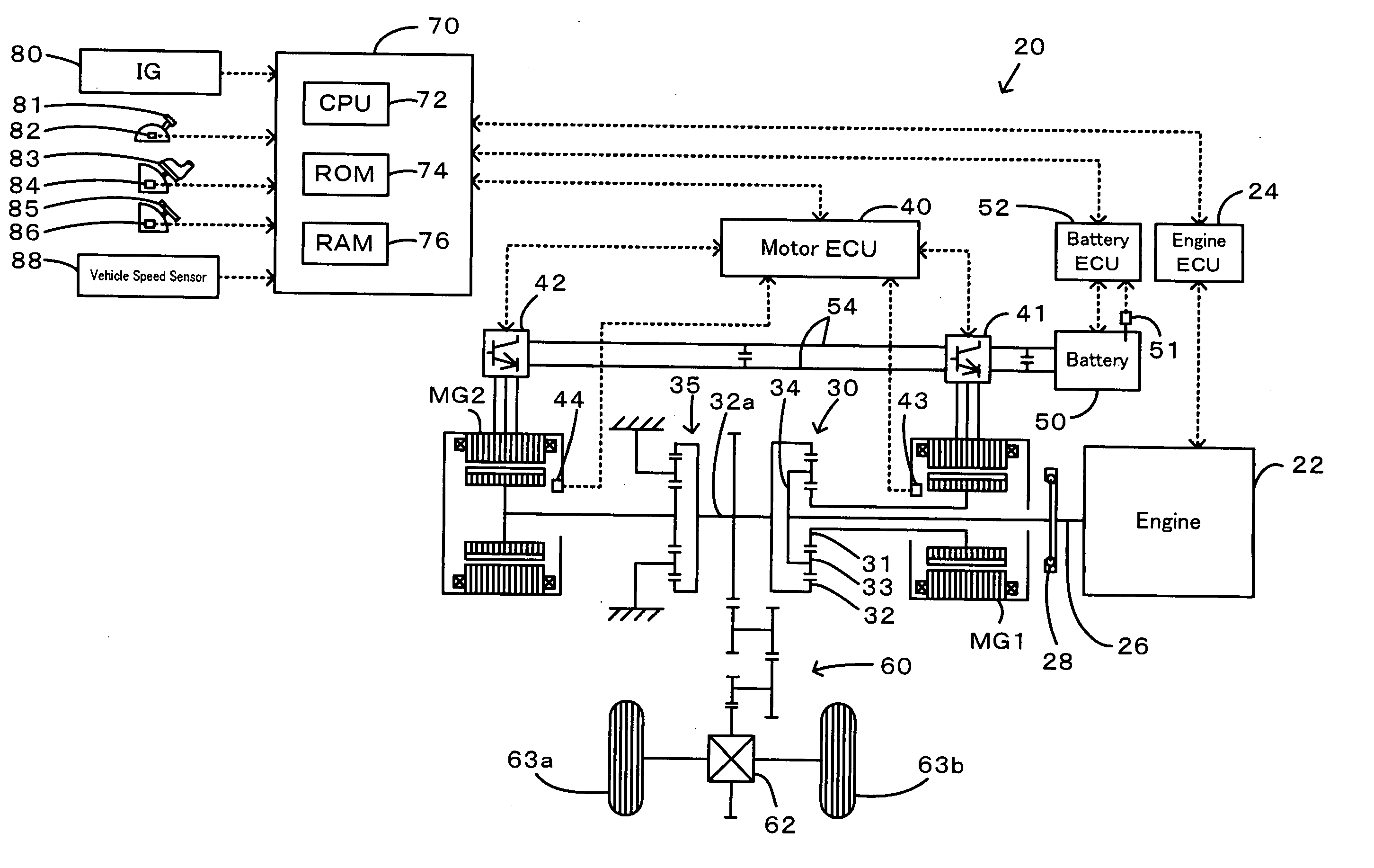
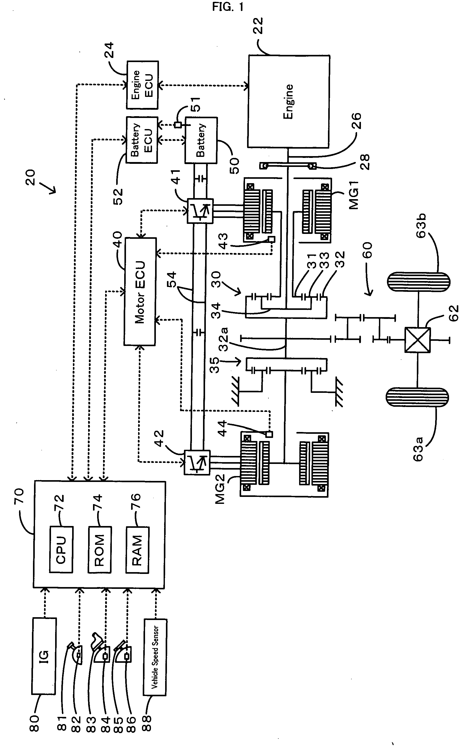
[0027] One mode of carrying out the invention is discussed below as a preferred embodiment. FIG. 1 schematically illustrates the construction of a hybrid vehicle 20 with a power output apparatus mounted thereon in one embodiment of the invention. As illustrated, the hybrid vehicle 20 of the embodiment includes an engine 22, a three shaft-type power distribution integration mechanism 30 that is linked with a crankshaft 26 functioning as an output shaft of the engine 22 via a damper 28, a motor MG1 that is linked with the power distribution integration mechanism 30 and is capable of generating electric power, a reduction gear 35 that is attached to a ring gear shaft 32a functioning as a drive shaft connected with the power distribution integration mechanism 30, another motor MG2 that is linked with the reduction gear 35, and a hybrid electronic control unit 70 that controls the whole power output apparatus.

[0028] The engine 22 is an internal combustion engine that uses a hydrocarbon ...


PUM


Abstract

When the current input and output charge levels of a battery are out of allowable input and output ranges, the drive control of the invention uses an operation curve under battery restriction, which sets the higher rotation speed in a low power range and has a smaller variation in rotation speed against a variation of output power than an operation curve in the ordinary state, to set a target rotation speed Ne* and a target torque Te* of an engine and controls the engine and motors MG1 and MG2. Application of this operation curve under battery restriction enhances the response of the engine to a variation of engine power demand Pe* and decreases a potential insufficiency of power due to a delayed response of the engine. The battery can thus input and output a required electric power within the ranges of an input limit Win and an output limit Wout to ensure supply of the insufficient power from the motor MG2. This control enables smooth output of a required power to a driveshaft.

Description

TECHNICAL FIELD [0001] The present invention relates to a power output apparatus, a motor vehicle equipped with the power output apparatus, and a control method of the power output apparatus. BACKGROUND ART [0002] One proposed structure of a power output apparatus includes an engine, a planetary gear unit including a carrier and a ring gear respectively connected with a crankshaft of the engine and with a driveshaft, a first motor linked to a sun gear of the planetary gear unit, a second motor linked to the driveshaft, and a battery having the capability of transmitting electric power to and from the first motor and the second motor (see, for example, Japanese Patent Laid-Open Gazette No. 2004-144041). The power output apparatus of this structure sets a lower limit to a power level of driving the engine at an optimum efficiency and makes control to keep a target engine power at or above the lower limit, in order to enhance the energy efficiency. DISCLOSURE OF THE INVENTION [0003] In...

Claims


Application Information

Patent Timeline
Patent Type & Authority Applications(United States)
IPC IPC(8): G06F19/00B60K6/00B60K6/445B60K6/448B60K6/52B60K17/04B60L50/16B60W10/04B60W10/06B60W10/08B60W10/10B60W10/101B60W10/26B60W20/00F02D29/00F02D29/02F02D45/00F16H48/10F16H61/02F16H63/50
CPCB60K6/445Y02T10/6239B60K6/48B60L11/08B60L11/123B60L11/14B60L11/1861B60L2220/14B60W10/06B60W10/08B60W10/26B60W20/00B60W2510/244F02D29/02Y02T10/6217Y02T10/6221Y02T10/6243Y02T10/6286Y02T10/646Y02T10/7005Y02T10/7022Y02T10/7044Y02T10/705Y02T10/7077Y02T10/648B60K6/448B60L50/13B60L50/61B60L50/16B60L58/12Y02T10/62Y02T10/70Y02T10/7072B60W20/10Y02T10/64
Inventor KIKUCHI, YOSHIAKI
Why Eureka
Try Eureka