
Light Emission Measuring Apparatus and Light Emission Measuring Method

a technology of light emission measurement and measuring apparatus, which is applied in the direction of luminescent dosimeters, optical radiation measurement, instruments, etc., can solve the problems of no conventional system for automatically reproducing the setting of optics, high cost, and long operation time, and achieve the effect of long operation time and complex operation

Inactive Publication Date: 2007-11-08
OLYMPUS CORP
View PDF0 Cites 5 Cited by
  • Summary
  • Abstract
  • Description
  • Claims
  • Application Information

AI Technical Summary

Benefits of technology

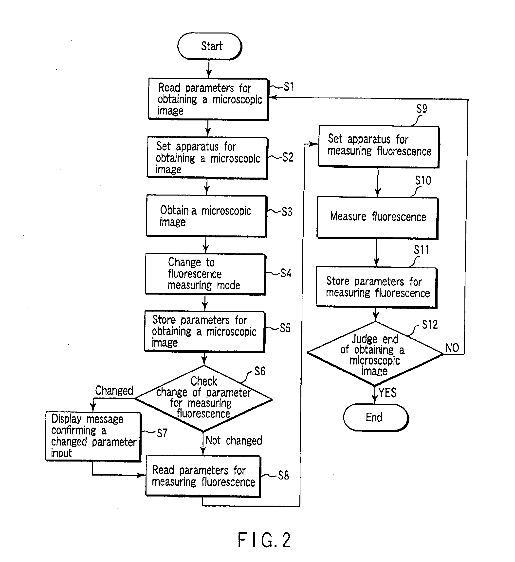
[0004] In correlation analysis of fluorescence at an optional point on a sample, a method of specifying an optional measuring point by a laser scanning microscopic image and obtaining a fluorescence correlation analysis value at that point is desired. Settings of filter, optical path and laser intensity used in optics of an analyzing apparatus are generally different for obtaining a microscopic image and measuring a fluorescence correlation. However, there is no conventional system for automatically reproducing settings of optics for obtaining a microscopic image and optics for measuring a fluorescence correlation. Therefore, whenever obtaining a microscopic image and measuring a fluorescence correlation are switched, the operator must change many settings of optics by himself. This makes the operation complex, and takes much time.
[0005] The present invention has been made to solve the above problems. Accordingly, it is an object of the invention to provide a light emission fluctuation measuring apparatus and method capable of improving convenience in switching measurement of a microscopic image and measurement of fluorescence fluctuation.

Problems solved by technology

However, there is no conventional system for automatically reproducing settings of optics for obtaining a microscopic image and optics for measuring a fluorescence correlation.
This makes the operation complex, and takes much time.

Method used


Image

  • Light Emission Measuring Apparatus and Light Emission Measuring Method
  • Light Emission Measuring Apparatus and Light Emission Measuring Method
  • Light Emission Measuring Apparatus and Light Emission Measuring Method

Examples


Embodiment Construction

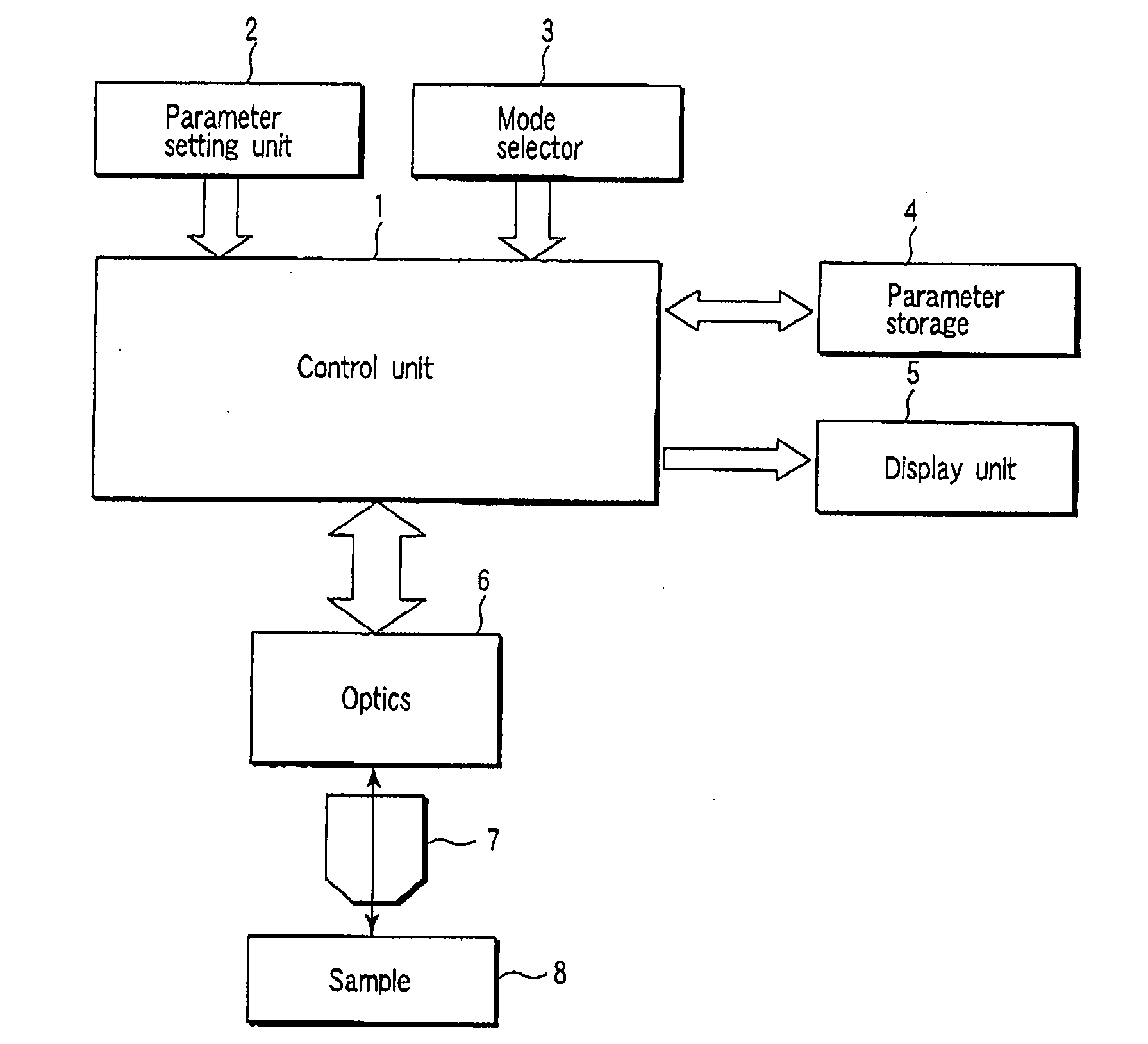
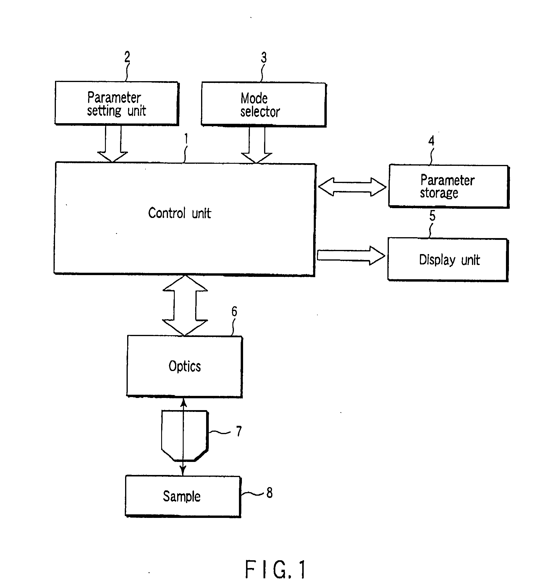
[0053] Embodiments of the invention will be explained in detail hereinafter with reference to the accompanying drawings. FIG. 1 shows the basic configuration of a light emission measuring apparatus according to the invention. The apparatus observes in time sequence and measures the fluctuation and intensity of light emission from a sample 8 as an observation object. The light emission measuring apparatus is provided with a controller 1, a parameter setting unit 2, a mode selector 3, a parameter storage 4, a display 5, optics 6, and objective lens 7. The optics 6 and objective lens 7 include a microscopic image obtaining unit (LSM) which obtains a microscopic image under the condition set based on the input parameter, and a light emission measuring unit (FCS) which observes in time sequence light emission in a desired area of the sample 8 corresponding to the microscopic image. The parameter setting unit 2 sets a parameter of the microscopic image obtaining unit used to obtain a micr...


PUM


Abstract

A light fluctuation measuring apparatus, comprising a parameter setting unit 2 which sets parameters of a microscopic image obtaining unit and / or parameters of a light emission measuring unit used for observing light emission in a desired area of a sample in time series, a parameter storage 4 which stores parameters, a mode selector 3 which selects one of a microscopic image obtaining mode for obtaining a microscopic image by a microscopic image obtaining unit, and a light emission measuring mode for observing light emission in a desired area by a light emission measuring unit, and a control unit 1 which reads parameters stored in the storage 4 based on a selected mode, inputs the parameter to a microscopic image obtaining unit or a light emission measuring unit, and controls these units.

Description

TECHNICAL FIELD [0001] The present invention relates to a light emission measuring apparatus, such as a light emission fluctuation measuring apparatus, and a light emission measuring method. BACKGROUND ART [0002] About fluorescence correlation spectroscopy will be explained hereinafter as an analysis example of fluctuation of fluorescence that is an example of light emission. Fluorescence correlation spectroscopy has been discussed in “Fluorescence Correlation Spectroscopy” R. Rigler, E. S. Elison (eds.) Springer (Berlin), “Protein, Nucleic Acid, Enzyme” (1999) Masataka Kinjo Vo. 44, No, p1431-1437, and PCT National Publication No. 11-502608. An apparatus for fluorescence correlation spectroscopy is often manufactured on the basis of a confocal optical microscope. A confocal optical microscope has been discussed in “Confocal Microscopy” T. Wilson (ed.) Academic press (London). A laser scanning confocal optical microscope that is a kind of confocal optical microscope may be used as a...

Claims


Application Information

Patent Timeline
Patent Type & Authority Applications(United States)
IPC IPC(8): G02B27/40
CPCG01N21/6458G02B21/16G02B21/0076G01N2201/10
Inventor SAWADA, RYUJINAKASHIMA, YOSHIO
Owner OLYMPUS CORP
Learn More