Matched impedance shielded pair interconnection system for high reliability applications

Active Publication Date: 2007-11-08
DEUT ENGINEERED CONNECTING DEVICES
View PDF2 Cites 74 Cited by
  • Summary
  • Abstract
  • Description
  • Claims
  • Application Information

AI Technical Summary

Benefits of technology

[0011] The present invention satisfies the need for an improved interconnection system by providing a connector that carries

Problems solved by technology

Despite the prevalence and low cost of the RJ-45 connector, it also has many limitations.
One drawback is that the wires have to be untwisted in order to be inserted into the jack.
By untwisting the wires, even if over a small length of cable, the wires become susceptible to signal degradation due to crosstalk.
Another drawback of the RJ-45 connection is that the connector is not environmentally sealed.
The wires that terminate at the end of the jack are exposed to the environment and can bec

Method used


Image

  • Matched impedance shielded pair interconnection system for high reliability applications
  • Matched impedance shielded pair interconnection system for high reliability applications
  • Matched impedance shielded pair interconnection system for high reliability applications

Examples


Embodiment Construction

[0036] The invention satisfies the need for a matched impedance shielded pair interconnection system for high speed data transmission. In the detailed description that follows, like element numerals are used to describe like elements shown in one or more of the figures.

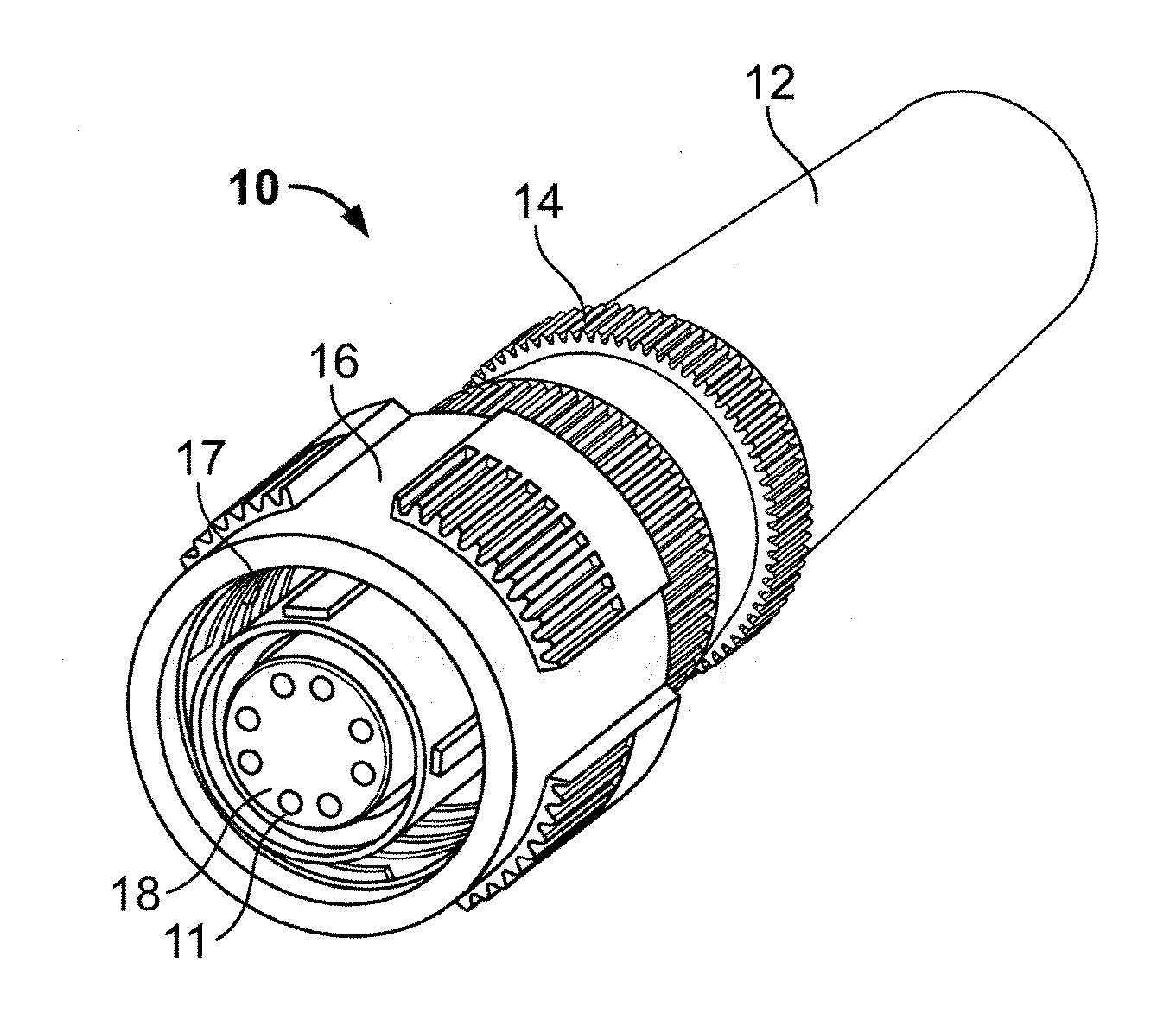
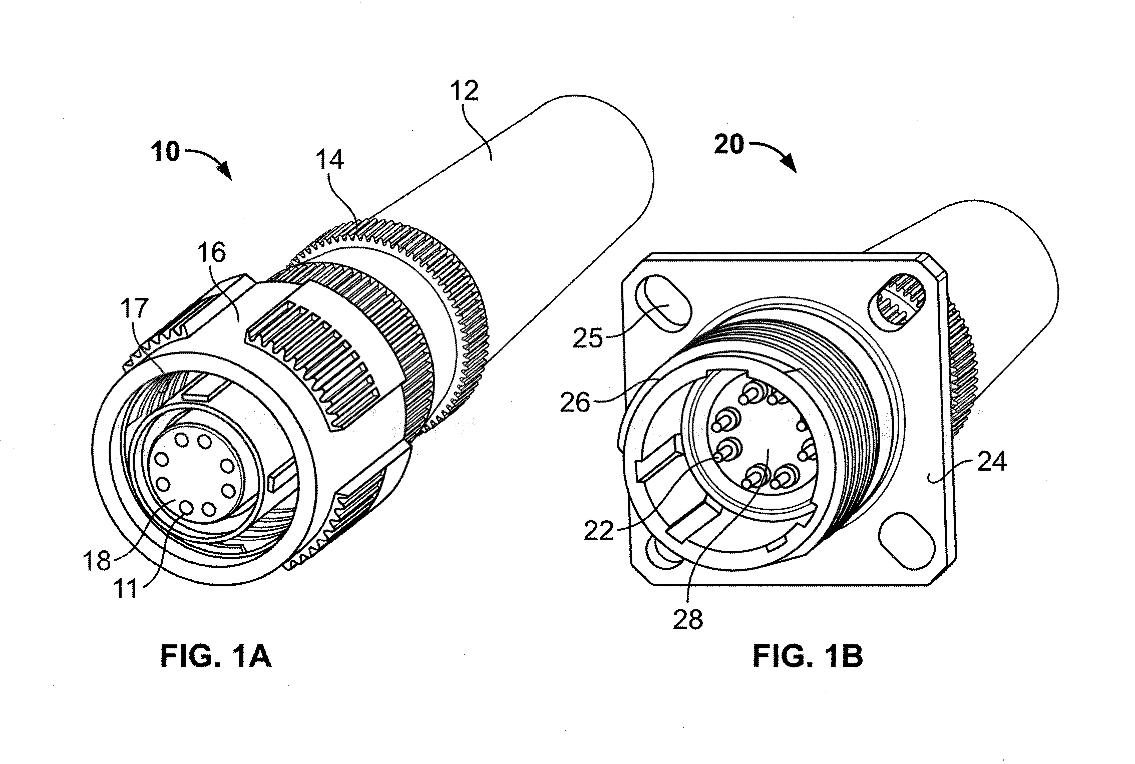
[0037] In a first embodiment of the present invention, a connection system includes a plug 10 (shown in FIG. 1A) and a receptacle 20 (shown in FIG. 1B). The plug 10 and receptacle 20 are arranged to be coupled together to form an electrical connection between plural pairs of conductors. The plug 10 has a generally cylindrical outer shell comprising boot 12 and coupling nut 14, with one or more knurled bands circumscribing the outer perimeter of the coupling nut 14 to facilitate gripping. The outer shell has an outside diameter that is commonly referred to as a geometric shape such as a round Size 11 (i.e., 0.985 inches). The plug 10 further includes a rotatable collar 16 at a distal end thereof. The collar 16 has int...


PUM


Abstract

A connector provides for attachment to a cable having a plurality of wires arranged in matched pairs. The connector comprises a housing and a connector insert located within the housing and having a plurality of contact cavities extending in an axial direction entirely therethrough. The connector insert further includes a substantially centrally located elongated opening extending in the axial direction from a proximal end thereof at least partially through the connector insert. The plurality of contact cavities are arranged substantially symmetrically with respect to the elongated opening. A conductive post is inserted into the elongated opening of the connector insert. The conductive post has elongated edges that provide shielding between respective pairs of the plurality of contact cavities. A follower is coupled to the conductive post. The follower has a plurality of passageways adapted to communicate respective ones of the matched pairs of wires to respective ones of the pairs of contact cavities. The follower thereby provides shielding between the respective pairs of wires. The connector further comprises a plurality of electrical contacts inserted into the respective ones of the plurality of contact cavities. The plurality of electrical contacts are adapted to be coupled to respective ones of the plurality of wires.

Description

RELATED APPLICATION DATA [0001] This patent application claims priority pursuant to 35 U.S.C. § 119(e) to U.S. provisional patent application Ser. No. 60 / 717,003, filed Sep. 13, 2005. BACKGROUND OF THE INVENTION [0002] 1. Field of the Invention [0003] The present invention is directed towards connection systems for communicating electrical signals, and more particularly, to a high-reliability, matched impedance, shielded-pair interconnection system adapted for high speed data transmission up to and exceeding one gigabit per second for protocols such as Ethernet, 1394, USB, 1553, Fibre Channel, VME, Can-Buss, J1708, and the like. [0004] 2. Description of Related Art [0005] With the increasing demand and complexity of modern electronic systems in high reliability applications such as military and aerospace, there is a continuing need to incorporate more electronic equipment into a confined space, while at the same time ensuring reliability in harsh environments. In such applications, ...

Claims


Application Information

Patent Timeline
IPC IPC(8): H01R25/00
CPCH01R9/035H01R13/518H01R13/622H01R13/6477H01R13/6471H01R13/6473H01R13/6463H01R13/65915
Inventor MACKILLOP, WILLIAM JOHNFRIEDHOF, JAMES
Owner DEUT ENGINEERED CONNECTING DEVICES
Why Eureka
Try Eureka