Clock transfer device

a clock transfer and clock technology, applied in the direction of wave amplification devices, laser details, electrical equipment, etc., can solve the problems of difficult counting of existing electric circuitry, difficulty in transferring light, and existing electric circuitry to process ligh

Inactive Publication Date: 2007-11-15
NAT INST OF ADVANCED IND SCI & TECH
View PDF10 Cites 17 Cited by
  • Summary
  • Abstract
  • Description
  • Claims
  • Application Information

AI Technical Summary

Benefits of technology

[0013]It is an object of the present invention to provide a clock transfer device that can realize long-distance transfer of a reference clock generated based on a high-precision frequency standard toward a remote place.

Problems solved by technology

Since the optical frequency reaches 1015 Hz, it is very difficult for the existing electric circuitry to process the light because of its high-speed performance; hence, it is very difficult for the existing electric circuitry to perform counting.
Generally speaking, this is a very difficult problem.
A laser of 1.5 μm band may be used for a trial but cannot be used because of technological difficulty.
However, this technology needs a complex electronic control circuit, and it suffers from the occurrence of timing jitters having several tens of femtoseconds due to the operation speed limit of the electronic circuit.
This technology realizes only the repetition frequency transfer, whereas the offset frequency is not stabilized; hence, it is very difficult to transfer a frequency comb synchronized with a reference frequency.

Method used


Image

  • Clock transfer device
  • Clock transfer device
  • Clock transfer device

Examples


first embodiment

1. First Embodiment

[0049]Next, a clock transfer device according to a first embodiment of the present invention will be described with reference to FIG. 2 and FIGS. 3A to 3F.

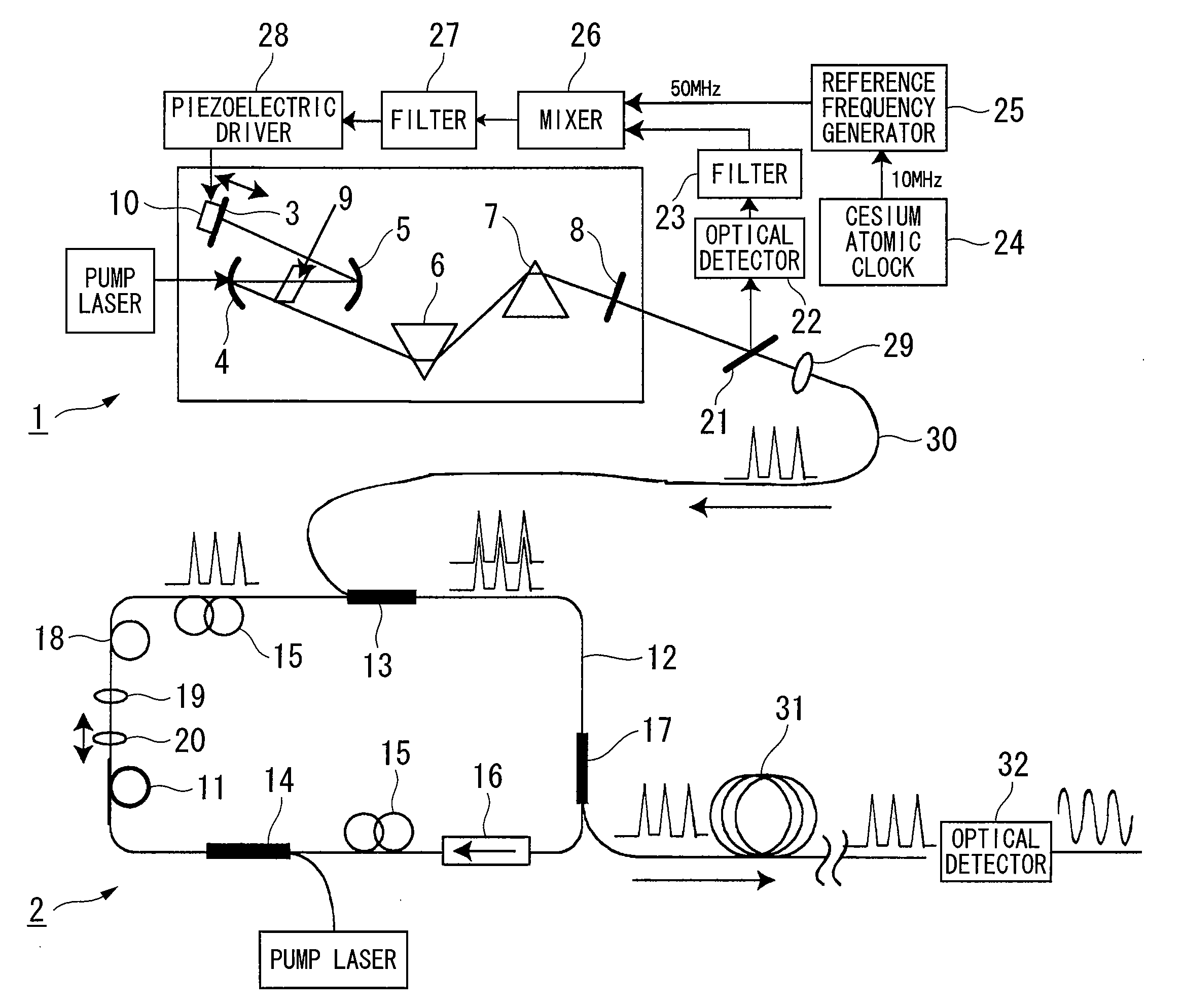
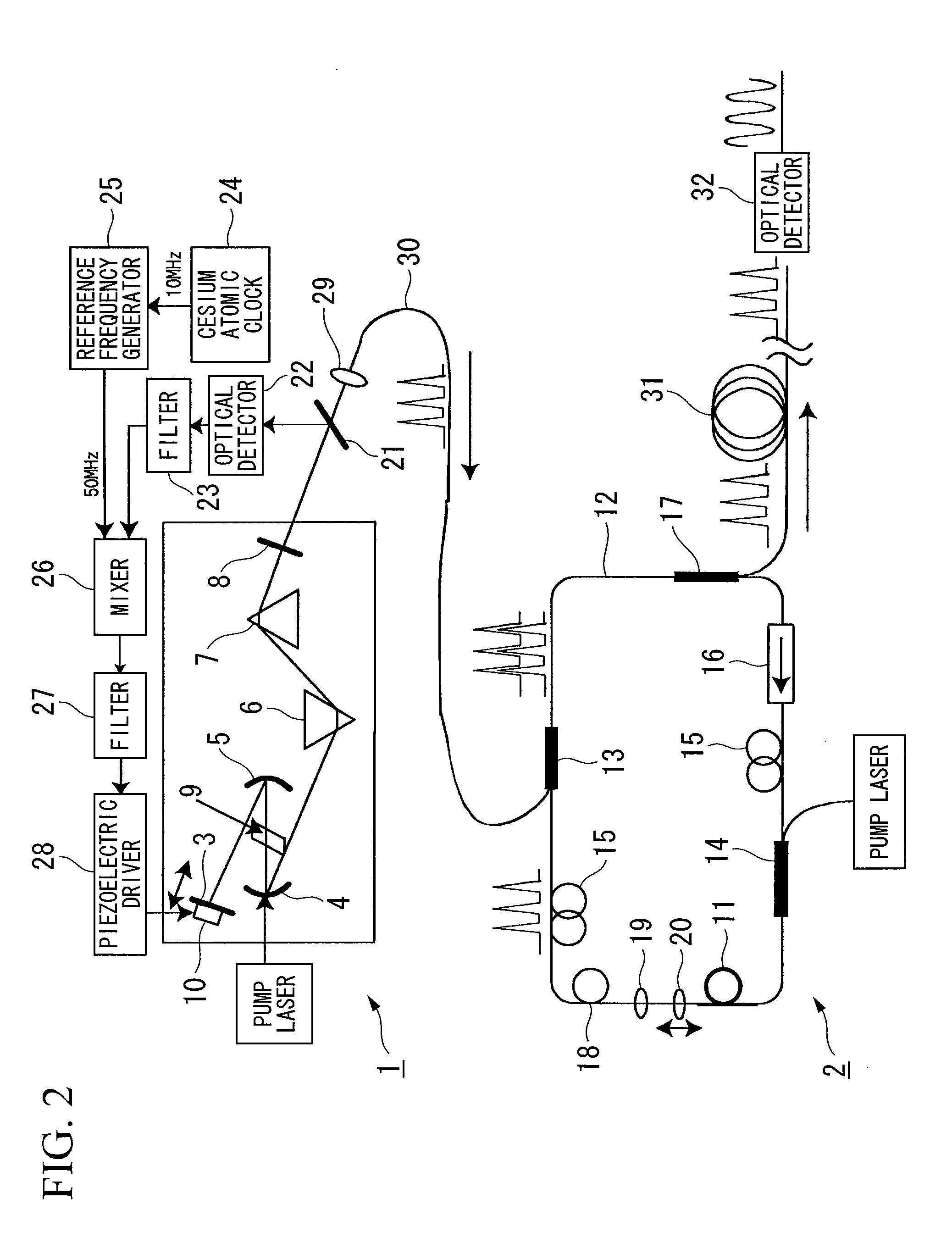
[0050]In FIG. 2, a 1.3 μm wavelength chrome-forsterite laser 1 serves as the first mode-locked laser forming the reference clock, and a 1.5 μm wavelength erbium fiber laser 2 serves as the second mode-locked laser. The first mode-locked laser includes a resonator, which is constituted of a mirror 3, concave mirrors 4 and 5, prisms 6 and 7, and an output mirror 8, and a chrome-forsterite crystal 9 serving as a laser medium. One pair of the prisms 6 and 7 compensates for the dispersion of laser beams in the resonator and is used to generate a mode-locked pulse train (or a mode-synchronized pulse train). The mirror 3 is mounted on a moving stage (not shown) and is used to adjust a resonator length. Apiezoelectric element 10 is attached to the backside of the mirror 3 so as to realize fine adjustment of the resonato...

second embodiment

2. Second Embodiment

[0057]Next, a clock transfer device according to a second embodiment of the present invention will be described with reference to FIGS. 4 and 5, wherein parts identical to those shown in FIG. 2 are designated by the same reference numerals; hence, the detailed description thereof is omitted as necessary.

[0058]In FIG. 4, an 800 nm wavelength titanium-sapphire laser 33 serves as the first mode-locked laser, and the aforementioned 1.5 μm wavelength erbium fiber laser 2 serves as the second mode-locked laser. The constitution of the first mode-locked laser used in the second embodiment is substantially identical to the constitution of the chrome-forsterite laser 1 used in the first embodiment, whereas dispersion compensating mirrors 34 and 35 are used to perform dispersion compensation due to multiple reflection. Herein, the resonator length is appropriately determined so as to set the repetition frequency to 1 GHz.

[0059]The first optical pulse train output from the ...

third embodiment

3. Third Embodiment

[0069]Next, a clock transfer device according to a third embodiment will be described with reference to FIG. 6.

[0070]In FIG. 6, the repetition frequency of the first optical pulse train output from the first mode-locked laser is set to 40 MHz, and the repetition frequency of the second optical pulse train output from the second mode-locked laser is set to 60 MHz. Herein, every two optical pulses belonging to the first optical pulse train meet every three optical pulses belonging to the second optical pulse train at the same timing in the resonator of the second mode-locked laser. In addition, the triple of the repetition frequency (i.e., 40 MHz) of the first optical pulse train (where M=3) is synchronized with the double of the repetition frequency (i.e., 60 MHz) of the second optical pulse train (where N=2) at the same value, i.e., 120 MHz.


PUM


Abstract

A clock transfer device is designed to perform long-distance transfer of a reference clock, which is generated based on a high-precision frequency standard, toward a remote place. The clock transfer device includes a first mode-locked laser for generating a first optical pulse train having a first repetition frequency and a first wavelength, and a second mode-locked laser for generating a second optical pulse train having a second repetition frequency and a second wavelength. The first optical pulse train is introduced into a resonator of the second mode-locked laser via a wavelength multiplexing coupler so that the second repetition frequency is passively synchronized with the first repetition frequency; then, the second optical pulse train is transmitted via a single mode fiber.

Description

BACKGROUND OF THE INVENTION[0001]1. Field of the Invention[0002]The present invention relates to clock transfer devices, which are used in communication and measurement fields in particular and which perform long-distance transfer of reference frequency clock signals generated based on high-precision frequency standards in the form of optical pulse trains toward remote places.[0003]This application claims priority on Japanese Patent Application No. 2006-135156, the content of which is incorporated herein by reference.[0004]2. Description of the Related Art[0005]Present frequency standards are determined based on microwaves (whose frequencies are below 1010 Hz) resonating transitions of cesium atoms. The next-generation high-precision frequency standard is developed based on optical transition of cooling atoms realizing higher frequencies instead of microwave transition. The frequency precision depends upon Δf / f where f (Hz) denotes transition frequency, and Δf (Hz) denotes frequency...

Claims


Application Information

Patent Timeline
Patent Type & Authority Applications(United States)
IPC IPC(8): H01S3/098H01S3/10H01S3/13H04B10/556H04B10/508H04B10/524H04B10/58
CPCH01S3/06791H01S3/10092H01S3/1394H01S3/1121H01S3/1112
Inventor YOSHITOMI, DAIKOBAYASHI, YOHEITORIZUKA, KENJI
Owner NAT INST OF ADVANCED IND SCI & TECH
Why Eureka
Try Eureka