

Jig for baking ceramic honeycomb moldings
a technology of honeycomb structure and molding, which is applied in the field of baking moldings, can solve problems such as temperature differences inside the honeycomb structur
- Summary
- Abstract
- Description
- Claims
- Application Information
AI Technical Summary
Benefits of technology
Problems solved by technology
Method used
Image

Examples
examples
[0051]Next, concrete Examples and Comparative Examples will be given to confirm the effect of the invention.
examples 1 to 5
, Comparative Examples 1 to 3
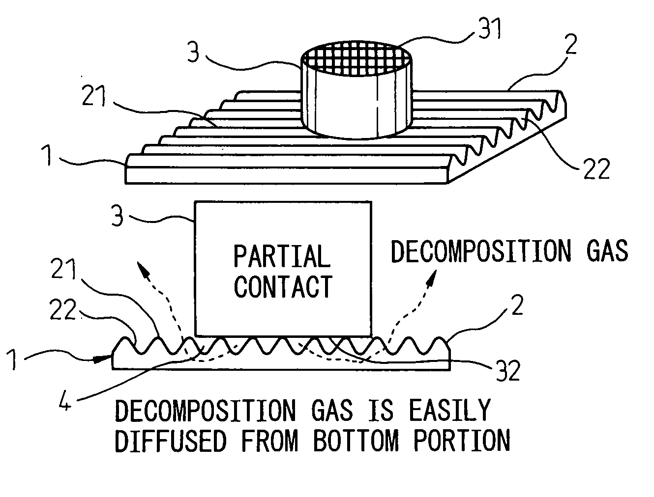
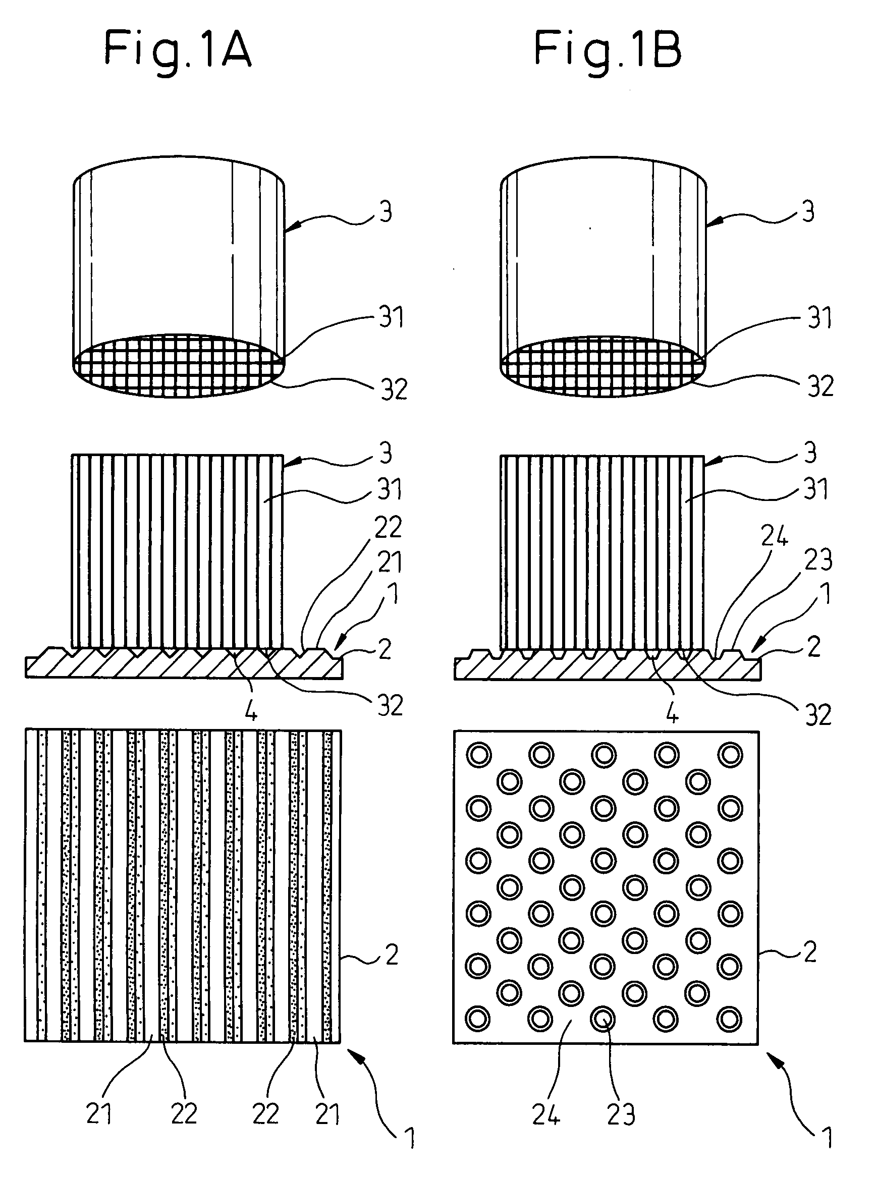
[0052]Baking of the ceramic honeycomb moldings 3 formed of cordierite was carried out by respectively using ceramic honeycomb molding baking jigs 1 having a corrugation shape shown in FIG. 1A and a projection shape shown in FIG. 1B. The baking jig 1 having the corrugation shape had convex portions 21 formed on an upper surface 2 of a ceramic body having a sheet thickness of 9 mm. The convex portion 21 had a height of 5 mm and a pitch gap was 10 mm. The contact area with the ceramic honeycomb molding 3 was changed by changing the width W of the flat top of the convex portion 21 to also change a communication ratio of cells 31. The baking jig 1 having the projection shape had a large number of substantially conical projection portions 23 formed on the upper surface 2 of the ceramic body having a sheet thickness of 9 mm as shown in FIG. 6. The projection portion 23 had a height of 5 mm and a pitch gap was 10 mm. The contact area with the ceramic honeycomb m...
PUM
| Property | Measurement | Unit |
|---|---|---|
| height | aaaaa | aaaaa |
| thickness | aaaaa | aaaaa |
| height | aaaaa | aaaaa |
Abstract
Description
Claims
Application Information