
Riding Floor Polishing and Grinding Machine for Treating Concrete, Terrazzo, Stone and Similar Surfaces

a technology for polishing machines and floors, applied in grinding machines, grinding/polishing apparatuses, manufacturing tools, etc., can solve the problems of increasing the effectiveness and efficiency of the polishing process, the inability of polishing and grinding machines to fully exploit the potentials of state-of-the-art polishing pads, and the ineffectiveness of machines, etc., to achieve more regulated vertical force, reduce the effect of reducing the number of cuts

Inactive Publication Date: 2007-11-15
BADGER MACHINE
View PDF1 Cites 15 Cited by
  • Summary
  • Abstract
  • Description
  • Claims
  • Application Information

AI Technical Summary

Benefits of technology

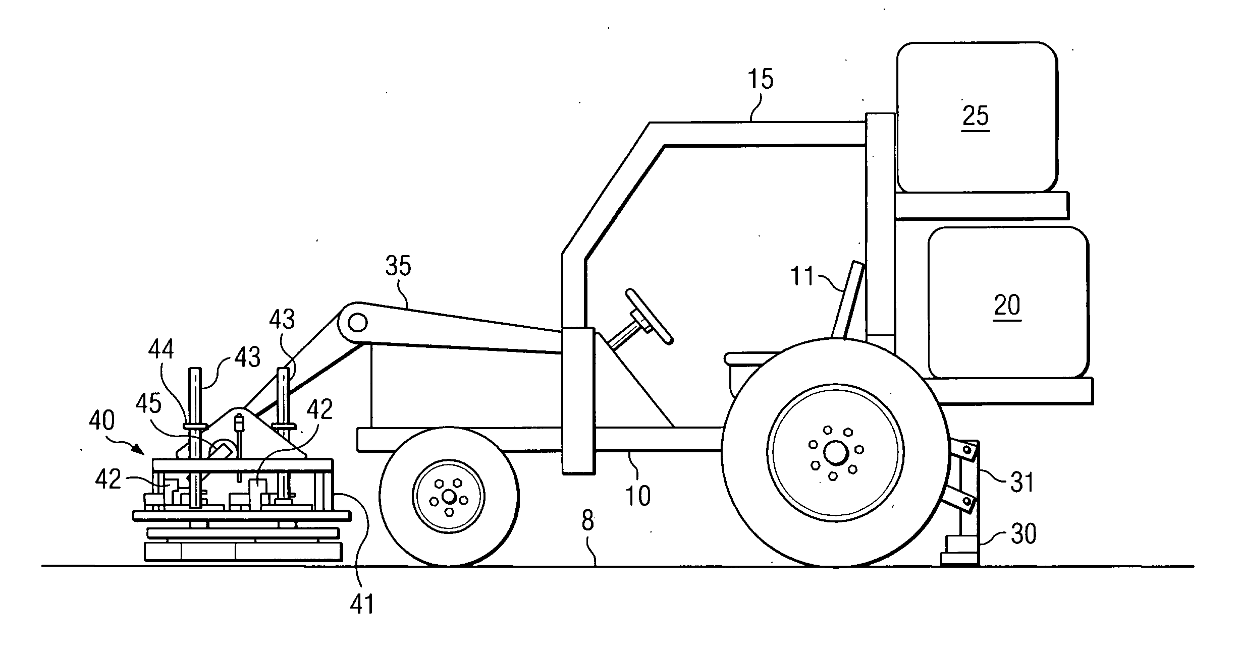
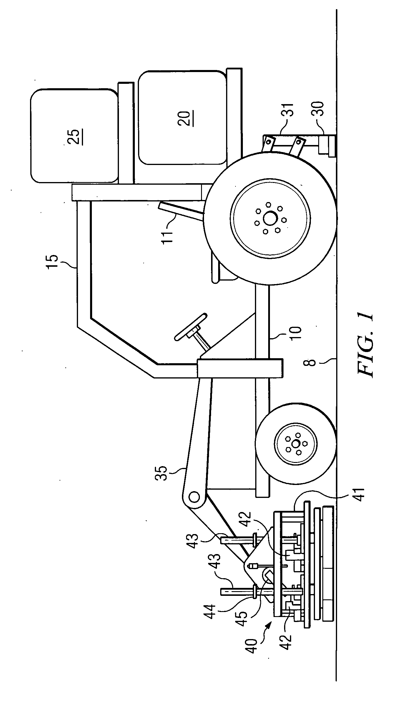
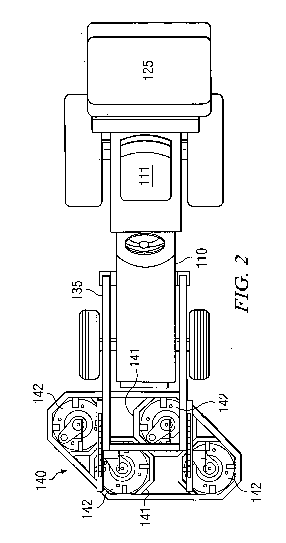
[0014] The gang module of four sander / polisher heads and their mounting frame are connected to the compact vehicle by front loader arms, often found on tractors. Mounting the gang module on the loader arms allows the mounting frame to lift and rotate so the gang module can be raised and tilted forward for easy removal to swap out the pads. The arms can apply more regulated vertical force on the grinding pads than previously available. Weights can be added to the module to provide sufficient vertical force onto the heads so that the pad's diamond abrasive can cut into the floor surface more effectively. The module is also mounted to tensioner arms to regulate the amount of vertical force delivered by the module to the floor surface. It is also possible to mount a second gang module with different grit-rated pads in place and perform two dissimilar floor treatment steps in the same operating pass.
[0015] Each of the heads is mounted onto a stationary center shaft that is center-drilled so that water and other treating solutions can be injected through the center of the spinning heads. Process water or other liquid solutions are fed from a 100 gallon or larger tank mounted on the back of the compact vehicle. A second storage tank is also mounted on the back of the compact vehicle and connected to a vacuum system that collects the used slurry generated by the grinding and polishing process. Alternatively, a single tank with two compartments can be used. A squeegee device on the back of the compact vehicle will also aid in collecting the slurry for vacuuming and cleaning the floor during the process.

Problems solved by technology

The industrial diamond abrasive incorporated into these pads greatly increases the effectiveness and the efficiency of the polishing process, so much so that existing floor polishing and grinding machines cannot fully exploit the potentials of these state-of-the art polishing pads.
Such machines are limited in effectiveness because of the limited size of floor area that can be polished and grinded in a given period of time.
The limited size of the buffer's polishing “footprint” is but one factor in the limited efficiency of a single operator using a floor buffer.
This inefficiency extends in large measure from an inability to fully exploit the enhanced polishing and grinding properties of the diamond-impregnated pads.
Also, the conventional single-pad floor buffer cannot exert sufficient vertical force onto the floor surface for the pad to dig into and grip the upper surface layer of the floor material for maximum grinding.
Nor can a conventional single-pad buffer develop sufficient rotational power to strip off the upper surface layer of the floor material to a sufficient degree.
It is also cost prohibitive to polish a very large floor area to the degree of smoothness now possible with the newer type of pads.
Moreover, if a conventional buffer machine could fully exploit the pads' potential, the forces exerted against the operator would be such that the operator could not control the buffer.
As such, it is difficult for an operator to control the buffer and achieve a uniform finish over large areas, often leaving inclusions or “swirling” visible in sections of the flooring.
However, such efforts have not been successful.
Such modified machines lack the necessary rotational power, cannot exert optimal vertical pressure, and cannot effectively dispense polishing solution.
The RGS50 is not a satisfactory solution because it fails to adequately dispense water or polishing solution.
It is limited in its grinding wheel configuration, and the amount of vertical force applied to the grinding surface is not well-regulated.
Thus, the RGS50 has trouble performing the grinding operation without leaving inclusions, swirling, or other imperfections in the surface.
The RGS50 also has a limited capacity for water or polishing solution.

Method used


Image

  • Riding Floor Polishing and Grinding Machine for Treating Concrete, Terrazzo, Stone and Similar Surfaces
  • Riding Floor Polishing and Grinding Machine for Treating Concrete, Terrazzo, Stone and Similar Surfaces
  • Riding Floor Polishing and Grinding Machine for Treating Concrete, Terrazzo, Stone and Similar Surfaces

Examples


Embodiment Construction

[0025]FIG. 1 is a side view showing the major elements of the inventions. The most prominent feature of the invention is the vehicle 10 that provides the essential structure for the invention. Although any basic small agricultural tractor with integrated or attached front loader arms and a power take off (PTO) output shaft can provide an acceptable base-line vehicle, the preferred embodiment utilizes a small or compact vehicle 10, preferably in the size range of 1200 to 2200 pounds, equipped with a 18 to 50 gross horsepower engine delivering at least 15 horsepower to the PTO output shaft. This size vehicle 10 has sufficient weight and power to properly grind and polish floors but is not so large as to be unwieldy and lack sufficient maneuverability for indoor applications, such as polishing the flooring in a warehouse, convention center, church, or even large residential house or multi-family dwelling. It may also be used on many construction jobs on upper floors and is not limited ...


PUM

PropertyMeasurementUnit
Weightaaaaaaaaaa
Weightaaaaaaaaaa
Forceaaaaaaaaaa

Abstract

The invention is a riding floor polishing and grinding machine that uses one or more gangs of polishing heads (242) to treat concrete and similar surface flooring (208). A compact vehicle (210) equipped with a front loader arm (235) is fitted with a module (240) containing the gang(s) of polishing head. The vehicle (210) is capable of raising and rotating the module to easily change the pads attached to the polishing heads. Each polishing head is individually powered by a motor and floats over the floor surface. The pads attached to the polishing heads can be of many different types, preferably diamond-impregnated polishing pads. The invention enables operator to more quickly and efficiently remove material from a floor surface. The design also enables gangs of pads to be mounted with different grit ratings to perform different treatment operations using a single machine in a single pass over a floor surface.

Description

TECHNICAL FIELD OF THE INVENTION [0001] A heavy-duty vehicle for grinding, polishing, and / or finishing concrete, terrazzo, stone, and similar surfaces. BACKGROUND OF THE INVENTION [0002] Portland cement was invented in 1824 by Englishman Joseph Aspdin, which became and has remained the dominant cement used in concrete construction. Concrete consists of a hard, chemically inert aggregate substance composed of sand and gravel bonded by cement and water. Aggregates found in concrete can include sand, crushed stone, gravel, slag, ashes, burned shale, crushed glass, and burned clay. Fine aggregate (fine refers to the size of aggregate) is used in making concrete slabs and smooth surfaces such as floors, while coarse aggregate is used for large structures or sections of cement. [0003] Over recent years, concrete and similar type flooring has enjoyed increasing popularity with expanding usage in both commercial and residential construction. Recent advances in polishing equipment and techni...

Claims


Application Information

Patent Timeline
IPC IPC(8): B24B27/00
CPCB24B55/12B24B7/186
Inventor LUNDBERG, THOMAS DAVIDWITHEM, MITCHELL STANLEY
Owner BADGER MACHINE
Learn More