Golf head and welding method thereof

a golf head and welding method technology, applied in the field of golf head and welding method thereof, can solve the problems of poor welding quality, relatively large gaps, and low production efficiency of the conventional method of welding the golf head, and achieve the effects of improving welding speed, improving welding quality, and improving welding speed

Inactive Publication Date: 2007-11-15
METAL INDS RES & DEV CENT
View PDF5 Cites 8 Cited by
  • Summary
  • Abstract
  • Description
  • Claims
  • Application Information

AI Technical Summary

Benefits of technology

[0012]The method of welding the golf head according to the present invention is achieved through a resistance welding method, and only one welding action is required. Therefore, the problem of the conventional fusion welding technique (e.g., plasma welding or laser welding) that it must weld along the weld and thus causing an overlong welding time is significantly improved. Therefore, the method of welding the golf head according to the present invention not only greatly enhances the welding speed, but also significantly increases the production efficiency. In addition, in the method of welding the golf head according to the present invention, the resistance welding method is used to make the metal body and the metal plate be mutually melted and combined, so as to eliminate the disadvantage of the conventional arc welding technique that the porosity and thermal cracks are generated at welding positions. Furthermore, the method of welding the golf head according to the present invention requires a low heat input, the deformation of work pieces is also relatively low, and there are no protruded weld, so that the golf head achieves a high flatness, and thus, the cost of the subsequent shaping and processing is reduced.

Problems solved by technology

Therefore, the conventional method of welding the golf head has relatively low production efficiency.
Furthermore, a tolerance is generated when the metal body 11 and the striking surface 12 are combined, which results in relatively large gaps.
Alternatively, the deformation generated in the heat-affected zone during the welding process easily causes the problem of a poor welding quality.
However, in the arc welding method, it must weld along the outline tracks of the metal body and the striking surface.
Therefore, similarly, a relatively long welding time is required, which causes the welding speed to be reduced, and thus, the production efficiency is relatively poor.
Furthermore, the arc welding technique can cause porosity and thermal cracks at welding positions, such that the strength for welding the golf head is affected.
As for the laser welding or the arc welding, a protruded weld is formed between the metal body and the striking surface after the welding process is finished, so that the time and manpower are required to perform the post processing of polishing the weld, and thus, the manufacturing cost is increased.

Method used


Image

  • Golf head and welding method thereof
  • Golf head and welding method thereof
  • Golf head and welding method thereof

Examples


Embodiment Construction

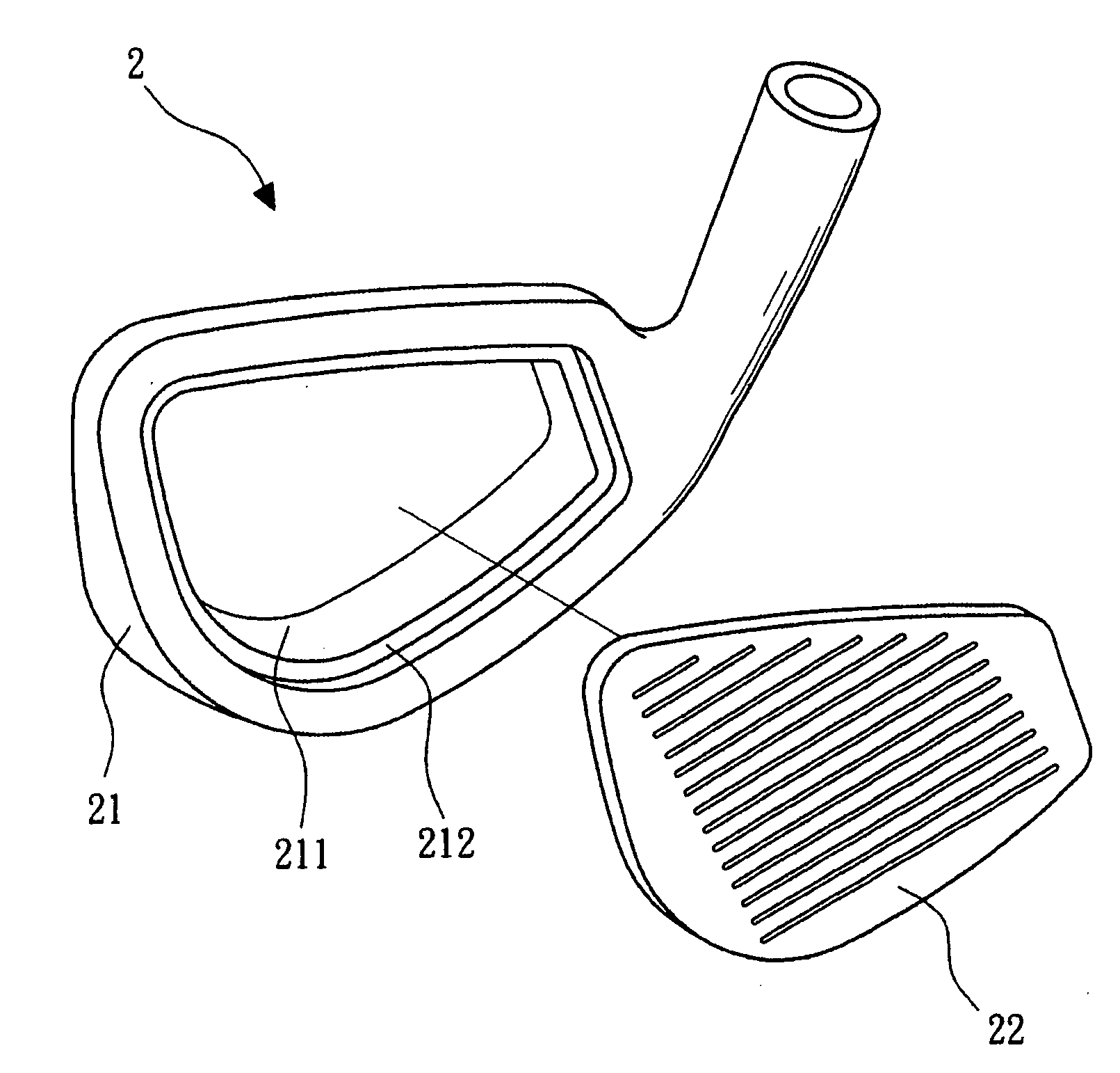
[0034]Referring to FIGS. 2A and 2B, they are schematic views of a golf head according to a first embodiment of the present invention. The golf head 2 comprises a metal body 21 and a metal plate 22. The metal body 21 has an opening 211 with a first welding surface 212. In the embodiment, the first welding surface 212 is configured to have a right angle. The shape of the metal plate 22 matches that of the opening 211. The metal plate 22 is a striking surface, and has a second welding surface 221 opposite to the first welding surface 212. The second welding surface 221 has at least one second bump 222. In the embodiment, the second bump 222 is an annular flange, as shown in FIG. 2C. In other applications, the second bump222 can also be a round protrusion, as shown in FIG. 2D, or an elongated bump, as shown in FIG. 2E.

[0035]It should be noted that, the first welding surface 212 can also have at least one first bump 213, as shown in FIG. 2F. Alternatively, the first bump 213 and the seco...


PUM

PropertyMeasurementUnit
shapeaaaaaaaaaa
shapesaaaaaaaaaa
porosityaaaaaaaaaa

Abstract

The present invention relates to a golf head and a welding method thereof. In the welding method of the invention, a metal plate is disposed in an opening of a metal body, wherein the shape of the metal plate matches that of the opening. Subsequently, a first electrode and a second electrode contact a back surface of the metal body and a top surface of the metal plate respectively, wherein the shapes of the first electrode and the second electrode match those of the back surface and the top surface respectively. Finally, the first electrode and the second electrode output a current so as to weld the metal body and the metal plate by a resistance welding process. By utilizing the welding method, the welding speed can be significantly increased so as to increase the yield, and the welded joint can be stronger. Furthermore, the welded golf head has a high flatness so that the following manufacturing cost can be decreased.

Description

BACKGROUND OF THE INVENTION[0001]1. Field of the Invention[0002]The present invention relates to a golf head and a welding method thereof, and more particularly to a golf head welded through a resistance welding method and a welding method thereof.[0003]2. Description of the Related Art[0004]Referring to FIGS. 1A to 1C, they are schematic views of a conventional method of welding a golf head. Referring to FIG. 1A, firstly, a metal body 11 is provided, which has an opening 111 with a ring groove 112. Referring to FIG. 1B, next, a striking surface 12 is provided. The shape of the striking surface 12 matches that of the opening 111, and the striking surface 12 is disposed on the ring groove 112. Referring to FIG. 1C, finally, a fusion welding technique (e.g., plasma welding or laser welding) is used, and in the embodiment, a laser beam 131 emitted by a laser apparatus 13 is used for welding along a track formed along the metal body 11 and the striking surface 12, so that a relatively l...

Claims


Application Information

Patent Timeline
Patent Type & Authority Applications(United States)
IPC IPC(8): A63B53/00
CPCA63B53/0475A63B2053/0416A63B2053/0462A63B53/047B23K11/002A63B53/0462A63B53/0416
Inventor WANG, LI-DETSAI, MENG-HSIUYANG, TZE-CHINGLU, MING-HSIENGLIN, CHIH-LUN
Owner METAL INDS RES & DEV CENT
Why Eureka
Try Eureka