Flexible circuit electrode array with at least one tack opening

a flexible circuit and electrode array technology, applied in flexible printed circuits, printed circuit aspects, therapy, etc., can solve the problems of retinal ischemia and hemorrhage, increase the electrical resistance between the array and the retina, and the dispersion of electric fields, so as to improve the electrical resistance, reduce the damage to the delicate retinal tissue, and improve the effect of electrical resistan

Active Publication Date: 2007-11-15
CORTIGENT INC +1
View PDF14 Cites 22 Cited by
  • Summary
  • Abstract
  • Description
  • Claims
  • Application Information

AI Technical Summary

Benefits of technology

[0016] The pressure applied against the retina, or other neural tissue, by an electrode array is critical. Too little pressure causes increased electrical resistance between the array and retina, along with electric field dispersion. Too much pressure may block blood flow causing retinal ischemia and hemorrhage. Pressure on the neural retina may also block axonal flow or cause neuronal atrophy leading to optic atrophy. Common flexible circuit fabrication techniques such as photolithography generally require that a flexible circuit electrode array be made flat. Since the retina is spherical, a flat array will necessarily apply more pressure near its edges, than at its center. Further, the edges of a flexible circuit polymer array may be quite sharp and cut the delicate retinal tissue. With most polymers, it is possible to curve them when heated in a mold. By applying the right amount of heat to a completed array, a curve can be induced that matches the curve of the retina. With a thermoplastic polymer such as liquid crystal polymer, it may be further advantageous to repeatedly heat the flexible circuit in multiple molds, each with a decreasing radius. Further, it is advantageous to add material along the edges of a flexible circuit array. Particularly, it is advantageous to add material that is more compliant than the polymer used for the flexible circuit array.
[0017] It is further advantageous to provide a fold or twist in the flexible circuit array at the point where it passes through the sclera. Additional material may be added inside and outside the fold to promote a good seal with the scleral tissue.

Problems solved by technology

Too little pressure causes increased electrical resistance between the array and retina, along with electric field dispersion.
Too much pressure may block blood flow causing retinal ischemia and hemorrhage.
Pressure on the neural retina may also block axonal flow or cause neuronal atrophy leading to optic atrophy.
Further, the edges of a flexible circuit polymer array may be quite sharp and cut the delicate retinal tissue.

Method used


Image

  • Flexible circuit electrode array with at least one tack opening
  • Flexible circuit electrode array with at least one tack opening
  • Flexible circuit electrode array with at least one tack opening

Examples


Embodiment Construction

[0042] The following description is of the best mode presently contemplated for carrying out the invention. This description is not to be taken in a limiting sense, but is made merely for the purpose of describing the general principles of the invention. The scope of the invention should be determined with reference to the claims.

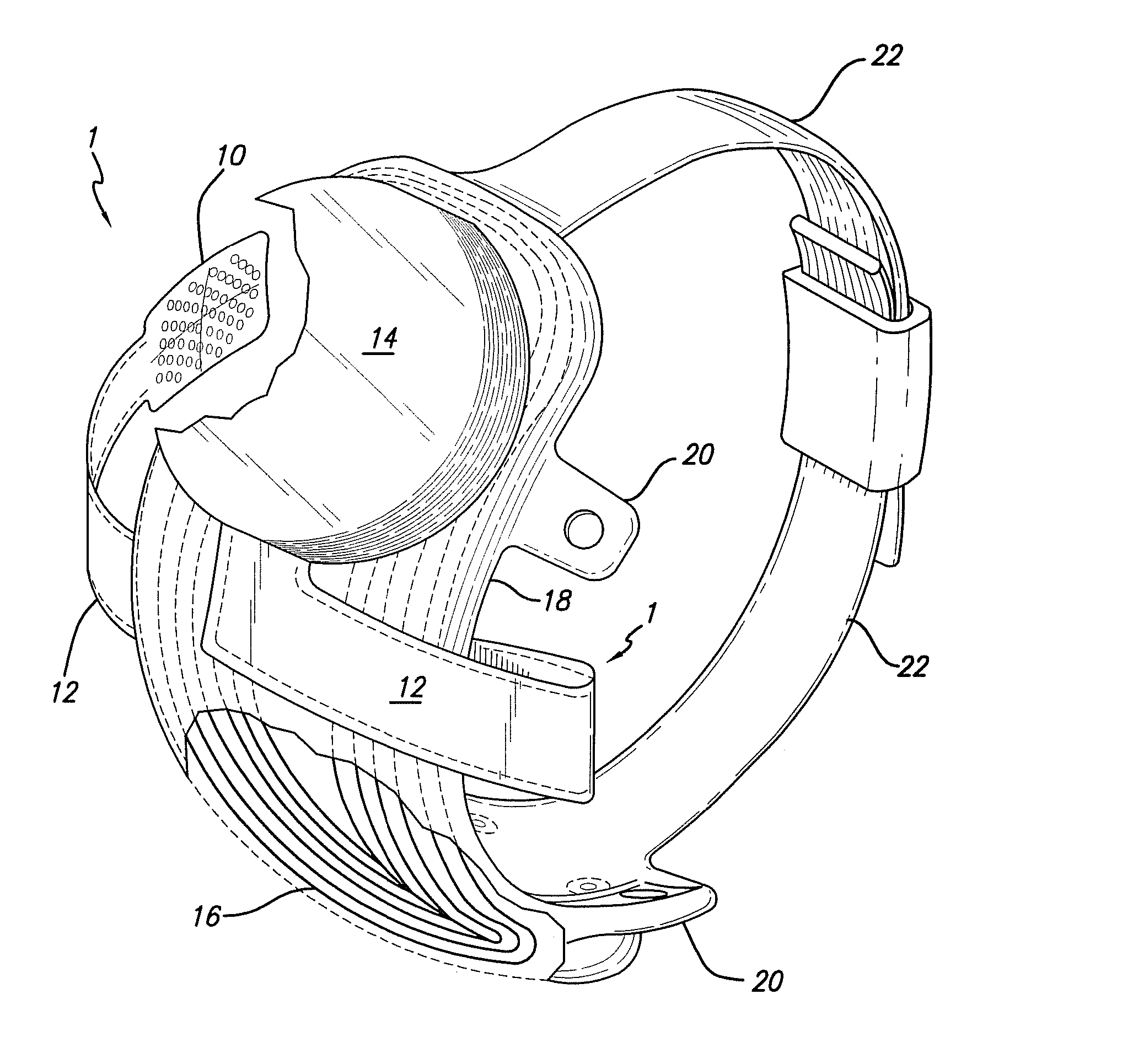
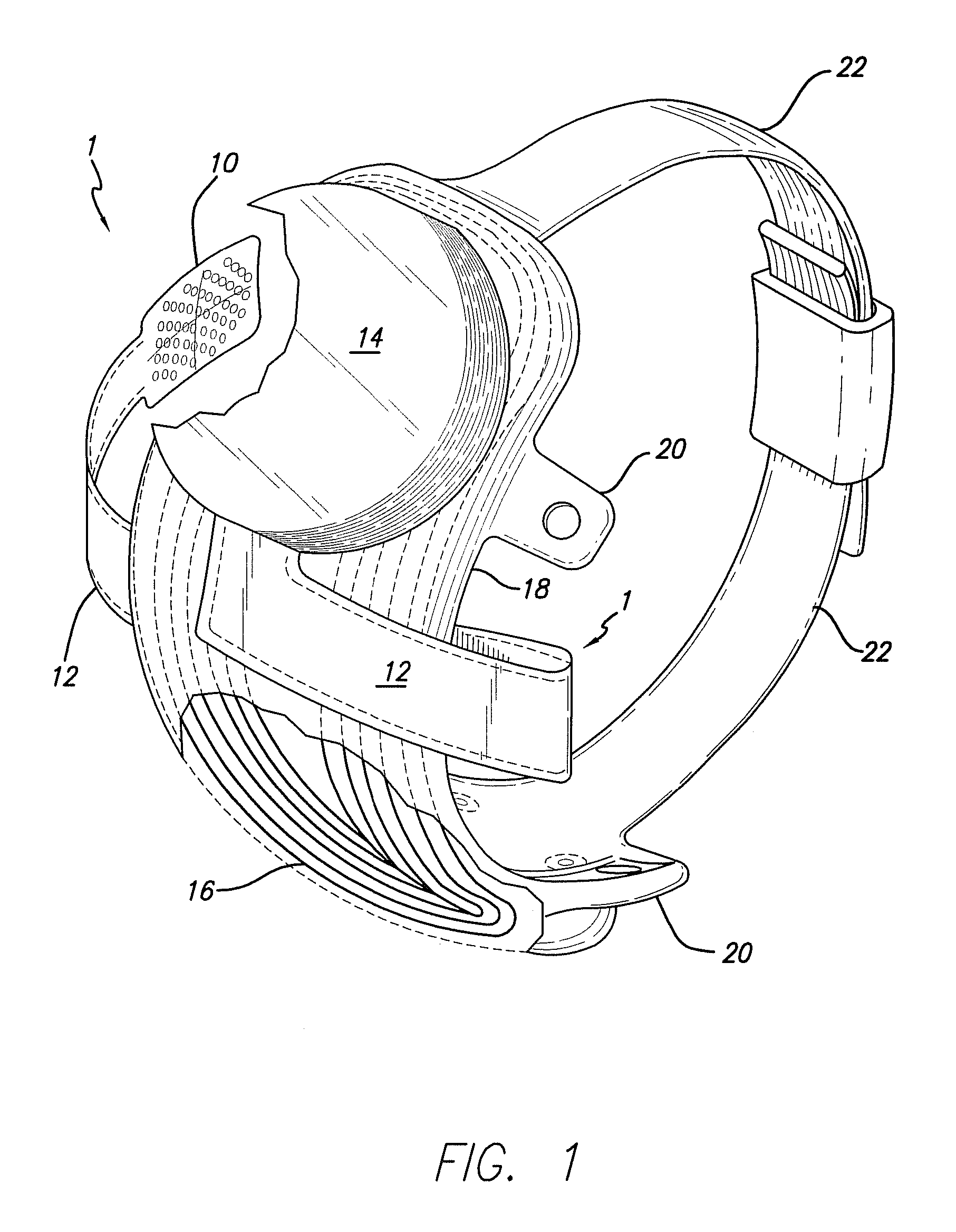
[0043]FIG. 1 shows a perspective view of the implanted portion of the preferred retinal prosthesis. A flexible circuit 1 includes a flexible circuit electrode array 10 which is mounted by a retinal tack (not shown) or similar means to the epiretinal surface. The flexible circuit electrode array 10 is electrically coupled by a flexible circuit cable 12, which pierces the sclera and is electrically coupled to an electronics package 14, external to the sclera.

[0044] The electronics package 14 is electrically coupled to a secondary inductive coil 16. Preferably the secondary inductive coil 16 is made from wound wire. Alternatively, the secondary inductive coi...


PUM

PropertyMeasurementUnit
angleaaaaaaaaaa
angleaaaaaaaaaa
flexibleaaaaaaaaaa

Abstract

The present invention provides a flexible circuit electrode array adapted for neural stimulation, comprising: a polymer base layer; metal traces deposited on said polymer base layer, including electrodes suitable to stimulate neural tissue; a polymer top layer deposited on said polymer base layer and said metal traces at least one tack opening; wherein said polymer base layer, said metal traces and said polymer top layer are thermoformed in a three dimensional shape. The present invention provides further a method of making a flexible circuit electrode array comprising depositing a polymer base layer; depositing metal on said polymer base layer; patterning said metal to form metal traces; depositing a polymer top layer on said polymer base layer and said metal traces; preparing at least one tack opening; and heating said flexible circuit electrode array in a mold to form a three dimensional shape in said flexible circuit electrode array.

Description

CROSS-REFERENCE TO RELATED APPLICATIONS [0001] This application claims the benefit of U.S. Provisional Application No. 60 / 815,311, “Flexible Circuit Electrode Array with at least one Tack Opening”, filed Jun. 21, 2006, the disclosure of which is incorporated herein by reference. [0002] This application is a Continuation-In-Part of U.S. application Ser. No. 11 / 413,689, “Flexible Circuit Electrode Array”, filed Apr. 28, 2006, which is a Continuation-In-Part of U.S. application Ser. No. 11 / 207,644, filed Aug. 19, 2005 which claims the benefit of U.S. Provisional Application No. 60 / 676,008, “Thin Film Electrode Array”, filed Apr. 28, 2005, the disclosures of all are incorporated herein by reference.GOVERNMENT RIGHTS NOTICE [0003] This invention was made with government support under grant No. R24EY12893-01, awarded by the National Institutes of Health. The government has certain rights in the invention.FIELD OF THE INVENTION [0004] The present invention is generally directed to neural s...

Claims


Application Information

Patent Timeline
Patent Type & Authority Applications(United States)
IPC IPC(8): A61N1/18
CPCA61N1/0543A61N1/36046H05K1/118H05K3/0014Y10T29/49117Y10T29/49155Y10T29/49002Y10T29/49174Y10T29/49176H05K1/036H05K1/0393H05K2201/05H05K2201/053H05K2201/09063H05K2201/09409Y10T29/49156Y10T29/49158
Inventor GREENBERG, ROBERT J.TALBOT, NEIL HAMILTONNEYSMITH, JORDAN MATTHEWLITTLE, JAMES SINGLETONMECH, BRIAN V.
Owner CORTIGENT INC
Why Eureka
Try Eureka