Air-conditioning unit and air-conditioning apparatus

a technology of air conditioning unit and air conditioner, which is applied in the direction of domestic cooling apparatus, vehicle heating/cooling device, vehicle components, etc., can solve the problems of difficult to satisfy the condition tdef>tfoot, the windshield cannot be heated to a sufficient temperature, etc., and achieves the effect of reducing mixing distance, easy flow, and increasing the temperature difference between the conditioned air in the high-temperature air channel and the low-temperature air channel

Inactive Publication Date: 2007-11-22
MITSUBISHI HEAVY IND LTD
View PDF5 Cites 26 Cited by
  • Summary
  • Abstract
  • Description
  • Claims
  • Application Information

AI Technical Summary

Benefits of technology

[0029]In this way, since the end-moving section is provided, the temperature difference between the air temperature at the high-temperature hot-air vent and the air temperature at the low-temperature hot-air vent can be adjusted.
[0030]Heated air flows from the side of the high-temperature air channel and cooled air flows from the side of the low-temperature air channel into the high-temperature air channel and the low-temperature air channel. Therefore, heated air easily flows into the high-temperature air channel compared with cooled air, whereas cooled air easily flows into the low-temperature air channel. The end-moving section can move the end position of the divider on the inflow side in a direction along the airflow. For example, when the end position is moved upstream of the...

Problems solved by technology

Thus, the windshield cannot be heated to a temperature sufficient for d...

Method used


Image

  • Air-conditioning unit and air-conditioning apparatus
  • Air-conditioning unit and air-conditioning apparatus
  • Air-conditioning unit and air-conditioning apparatus

Examples


first embodiment

[0057]A vehicle air-conditioning apparatus according to a first embodiment of the present invention will be described below with reference to FIGS. 1 to 6.

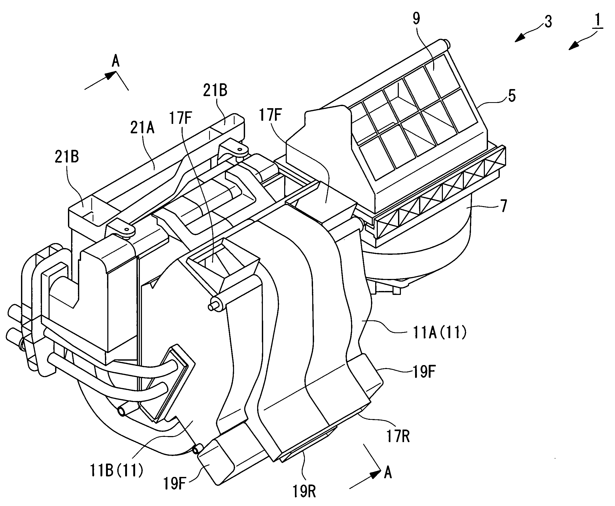
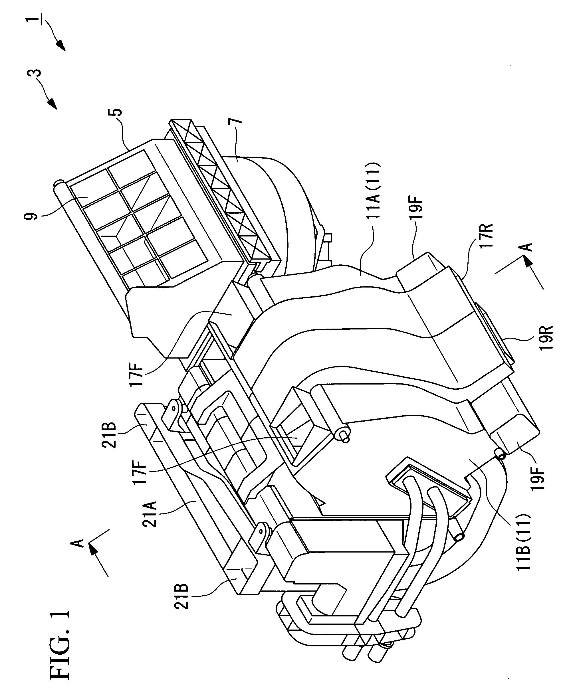
[0058]FIG. 1 is a perspective view illustrating the overall structure of an HVAC unit of the vehicle air-conditioning apparatus according to this embodiment.

[0059]As shown in FIG. 1, an interior / exterior-air switching box 5 and a blower fan 7 are attached to an HVAC unit (air-conditioning unit) 3 of a vehicle air-conditioning apparatus (air-conditioning apparatus) 1. An interior / exterior-air switching damper 9 is attached on the interior / exterior-air switching box 5. By operating the interior / exterior-air switching damper 9, the interior / exterior-air switching box 5 selectively takes in vehicle interior air (interior air) or vehicle exterior air (exterior air).

[0060]In the description below, unconditioned interior or exterior air taken in from the interior / exterior-air switching box 5 is collectively referred to as “intake air”, a...

first modification

of First Embodiment

[0114]Next, a first modification of the first embodiment will be described with reference to FIGS. 7 to 11.

[0115]The basic structure of the vehicle air-conditioning apparatus according to this modification is the same as that according to the first embodiment, except that the shape of the guide vane differs. Therefore, in this modification, only the shape of the guide vane and its vicinity will be described with reference to FIGS. 7 to 11, and descriptions of other components will be omitted.

[0116]FIG. 7 is a schematic view illustrating the positional relationship of a guide vane and a switching damper in an HVAC unit in a vehicle air-conditioning apparatus according to this modification.

[0117]Components according to this modification that are the same as those in the first embodiment will be represented with the same reference numerals.

[0118]As shown in FIG. 7, an HVAC unit (air-conditioning unit) 103 of a vehicle air-conditioning apparatus (air-conditioning appa...

second modification

of First Embodiment

[0156]Next, a second modification of the first embodiment of the present invention will be described with reference to FIG. 12.

[0157]The basic structure of a vehicle air-conditioning apparatus according to this modification is the same as that according to the first embodiment, except that the shape of the guide vane differs. Therefore, in this modification, only the shape of the guide vane and its vicinity will be described with reference to FIG. 12, and descriptions of other components will be omitted.

[0158]FIG. 12 is a schematic view illustrating the positional relationship of a guide vane and a switching damper in an HVAC unit in a vehicle air-conditioning apparatus according to this modification.

[0159]Components according to this modification that are the same as those in the first embodiment will be represented with the same reference numeral.

[0160]As shown in FIG. 12, an HVAC unit (air-conditioning unit) 203 of a vehicle air-conditioning apparatus (air-cond...


PUM


Abstract

An air-conditioning unit and an air-conditioning apparatus capable of setting the air temperature at a defroster vents higher than the air temperature at the foot vents during heating operation are provided. Each of the air-conditioning unit and air-conditioning apparatus includes a chassis; a cooling unit configured to cool air introduced into the chassis; a heating unit configured to heat air introduced into the chassis; a conditioned-air channel configured to guide the heated air and the cooled air into a high-temperature hot-air vent and a low-temperature hot-air vent; and a mixing-suppression unit configured to suppress mixing of the heated air and the cooled air, the mixing-suppression unit being provided in the conditioned-air channel.

Description

BACKGROUND OF THE INVENTION[0001]1. Field of the Invention[0002]The present invention relates to an air-conditioning unit and an air-conditioning apparatus.[0003]This application is based on Japanese Patent Application No. 2006-136234, the content of which is incorporated herein by reference.[0004]2. Description of Related Art[0005]Conventionally, there have been vehicle air-conditioning apparatuses that provide a comfortable interior environment for vehicles by carrying out air conditioning and dehumidification of the vehicle interior. Such vehicle air-conditioning apparatuses include a closed cooling cycle that is formed of a compressor that is operated using part of the output of the internal-combustion engine for driving the vehicle, a condenser that condenses a gas refrigerant by carrying out heat-exchange with air outside the vehicle (exterior air), an expansion valve that decompresses liquid refrigerant, and an evaporator that vaporizes the liquid refrigerant by carrying out ...

Claims


Application Information

Patent Timeline
IPC IPC(8): F25D9/00
CPCB60H1/00064B60H2001/00085B60H2001/00164B60H2001/00135B60H2001/00092
Inventor TADA, KATSUYOSHIMATSUBARA, SHIROIZUMI, HAJIMEEGUCHI, TSUYOSHI
Owner MITSUBISHI HEAVY IND LTD
Why Eureka
Try Eureka