Redundant Blade Pitch Control System for a Wind Turbine and Method for Controlling a Wind Turbine

Inactive Publication Date: 2007-11-22
GENERAL ELECTRIC CO
View PDF8 Cites 46 Cited by
  • Summary
  • Abstract
  • Description
  • Claims
  • Application Information

AI Technical Summary

Benefits of technology

[0011] In a preceding step, the rotor blade whose power control module is malfunctioning is brought into a parking position as well. To this end, the malfunctioned power control module is replaced by one of the intact power control modules by switching between these two power control modules. By operating in this mode, the pitch angle of each rotor blade can be successiv

Problems solved by technology

This decreases the aerodynamic lift on the rotor blades and therefore decreases the power output

Method used


Image

  • Redundant Blade Pitch Control System for a Wind Turbine and Method for Controlling a Wind Turbine
  • Redundant Blade Pitch Control System for a Wind Turbine and Method for Controlling a Wind Turbine
  • Redundant Blade Pitch Control System for a Wind Turbine and Method for Controlling a Wind Turbine

Examples


Embodiment Construction

[0027] Reference will now be made in detail to various embodiments of the invention, one or more examples of which are illustrated in the drawings. In the Figures and the description that follows, like reference numerals refer to similar elements. Each example is provided by way of explanation of the invention, and is not meant as a limitation of the invention. For example, features illustrated or described as part of one embodiment can be used on or in conjunction with other embodiments to yield yet a further embodiment. It is intended that the present invention include such modifications and variations. To describe the invention in more detail, reference is taken mainly to the pitch control method due to the fact that most of the current wind turbines are operated by using this method. However, the inventive blade pitch system can be used for active stall regulation as well.

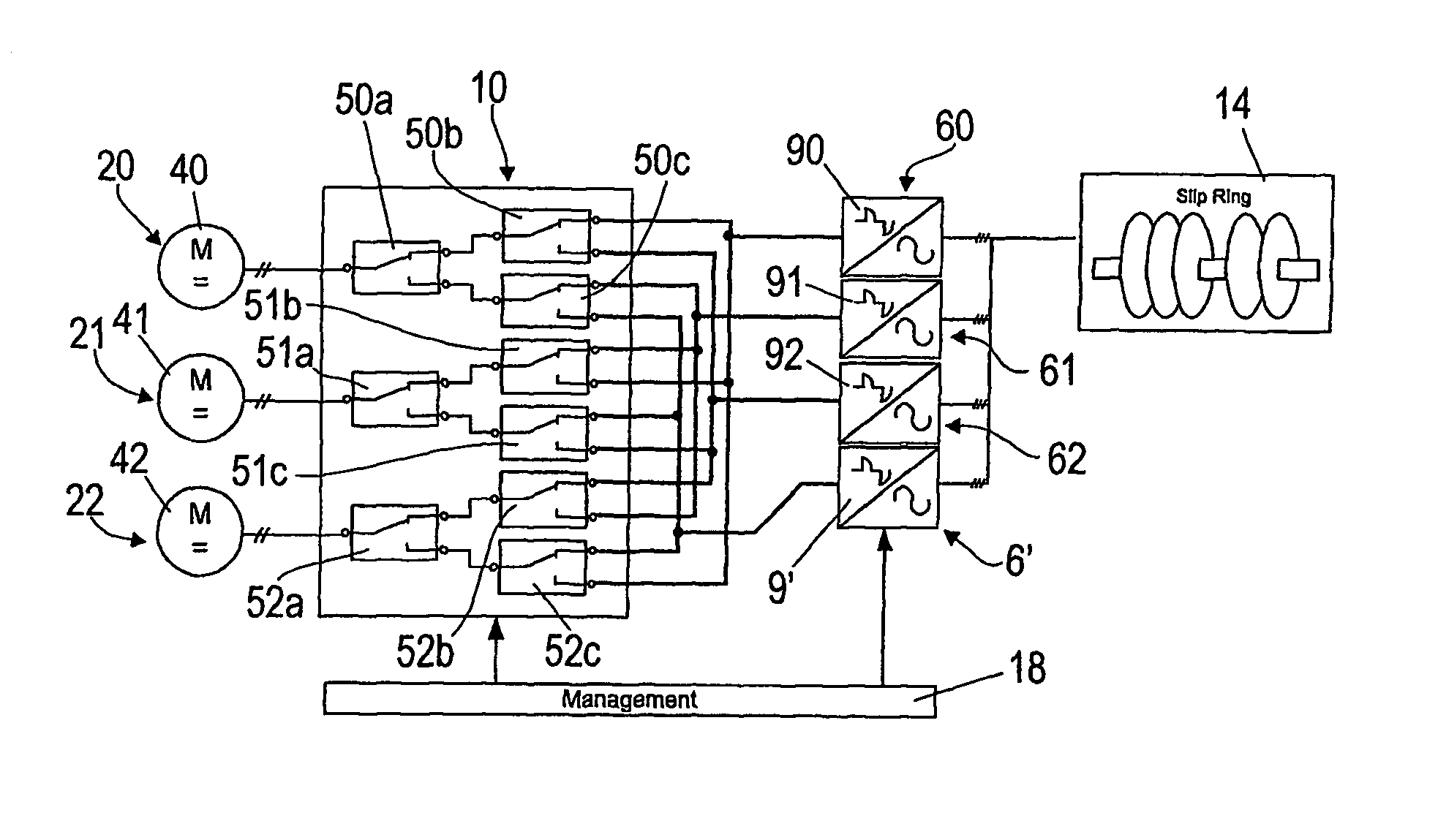
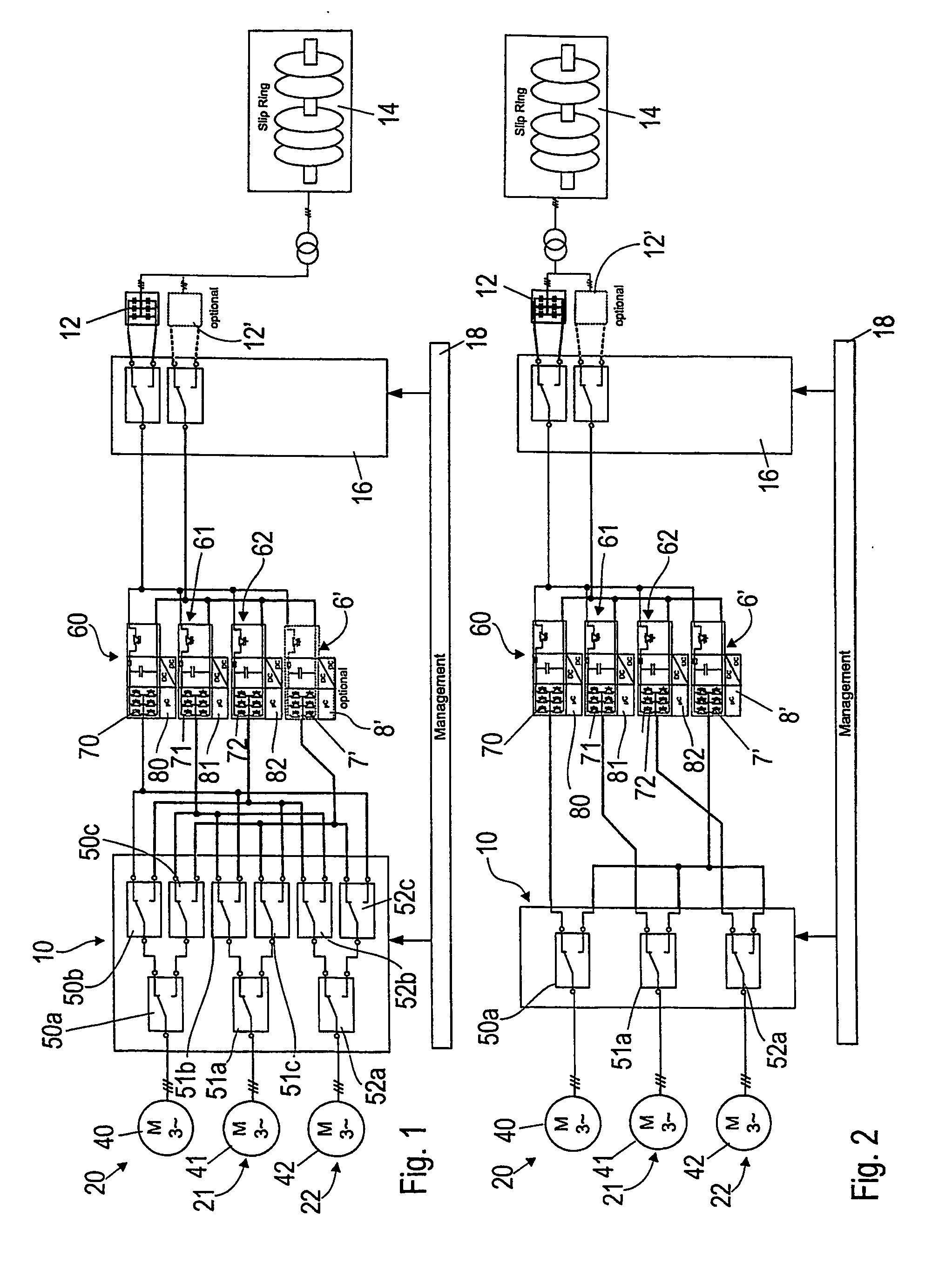
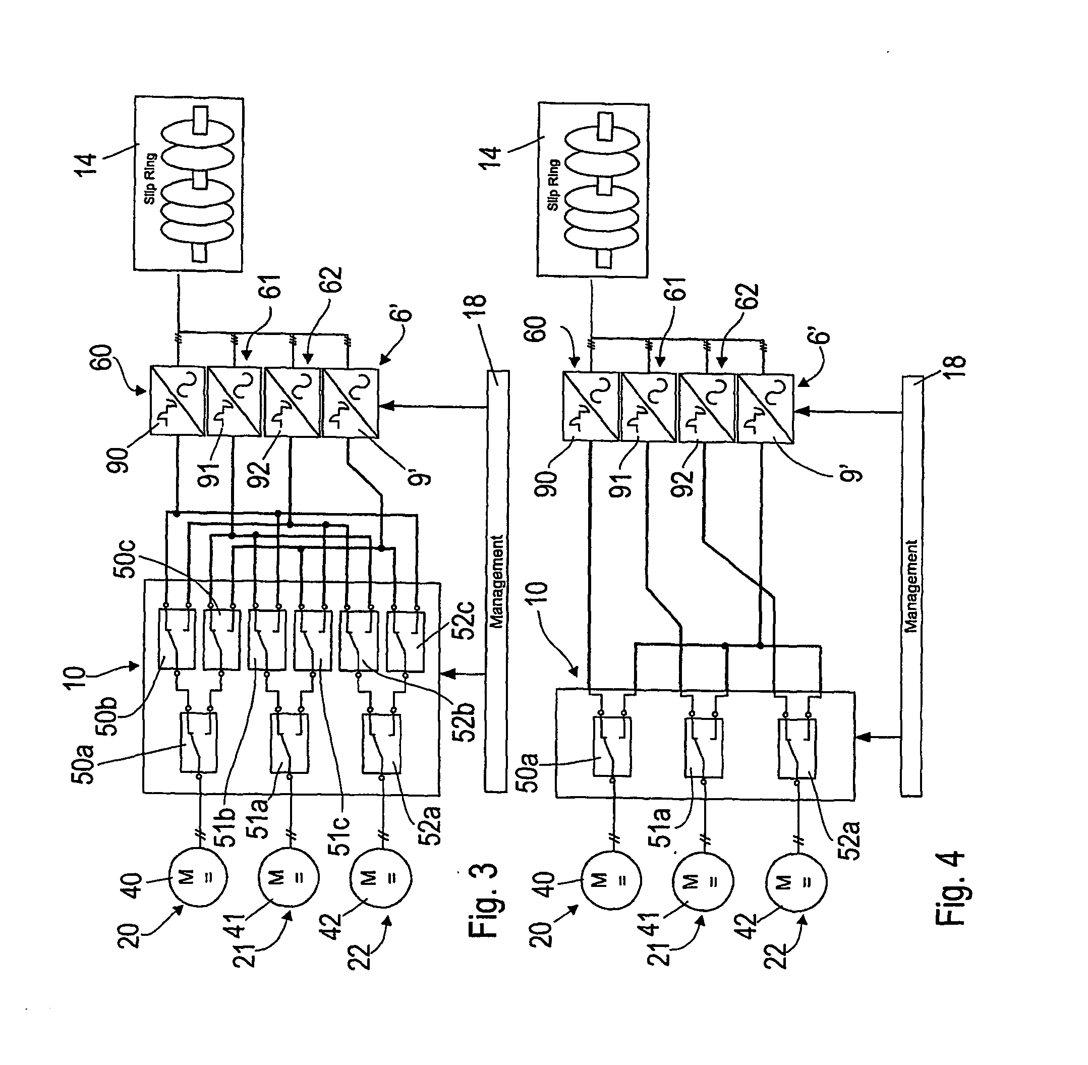
[0028]FIG. 1 shows a blade pitch system for a three rotor blade wind turbine. However, the system can be mo...


PUM


Abstract

A redundant and fail-safe blade system of a wind turbine includes at least one blade pitch drive (20, 21, 22) and at least two power control modules (60, 61, 62, 6′) for controlling the blade pitch drive (20, 21, 22). The power control modules (60, 61, 62, 6′) are connected to the blade pitch drive (20, 21, 22) by a switching unit (10) which allows an alternative connection between the blade pitch drive (20, 21, 22) and any of the power control modules (60, 61, 62, 6′). In operation, the blade pitch drive (20, 21, 22) is controlled by only one of the power control modules (60, 61, 62, 6′). If a malfunction of the currently operating power control module (60, 61, 62, 6′) is detected, switching unit (10) provides a connection to the other power control module (60, 61, 62, 6′) to allow an ongoing operation of the wind turbine without an unplanned or forced shut-down.

Description

FIELD OF THE INVENTION [0001] The present invention relates generally to a wind turbine and particularly to a blade pitch system of a wind turbine. BACKGROUND OF THE INVENTION [0002] Wind turbines are commonly used to convert kinetic energy of an air stream into electric energy. An essential part of a wind turbine is the rotor with its rotor blades, which captures the kinetic energy and converts it into rotational energy. The efficiency of uptake of kinetic energy mainly depends on the aerodynamic profile and the pitch angle of the rotor blades. In order to adjust the pitch angle, the rotor blades, which are rotatably mounted to the rotor's hub by a pitch bearing, can be rotated around their longitudinal axis by using a pitch drive. [0003] At very high wind speeds, the power captured from the wind by the rotor may exceed the limits set by the wind turbine's structural strength. Additionally, the generator's allowable maximum power constitutes a limit for the rotor's output power. Fu...

Claims


Application Information

Patent Timeline
IPC IPC(8): F03D9/00F03D7/02
CPCF03D7/0224F03D7/0264F05B2260/74F05B2260/76Y02E10/723F05B2260/845F05B2270/107F05B2270/1074F05B2270/602F05B2260/80Y02E10/72
Inventor MENKE, DETLEF
Owner GENERAL ELECTRIC CO
Why Eureka
Try Eureka