End-to-end design of superresolution electro-optic imaging systems

Active Publication Date: 2007-11-22
RICOH KK
View PDF44 Cites 188 Cited by
  • Summary
  • Abstract
  • Description
  • Claims
  • Application Information

AI Technical Summary

Benefits of technology

[0012] The present invention overcomes the limitations of the prior art by providing a superresolution electro-optic imaging system where the overall system takes into account the different subsystems. For example, rather than designi

Problems solved by technology

In single-frame systems, the superresolution band is

Method used


Image

  • End-to-end design of superresolution electro-optic imaging systems
  • End-to-end design of superresolution electro-optic imaging systems
  • End-to-end design of superresolution electro-optic imaging systems

Examples


Example

[0030] The figures depict embodiments of the present invention for purposes of illustration only. One skilled in the art will readily recognize from the following discussion that alternative embodiments of the structures and methods illustrated herein may be employed without departing from the principles of the invention described herein.

DETAILED DESCRIPTION OF THE PREFERRED EMBODIMENTS

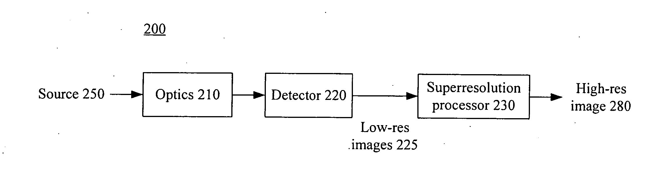
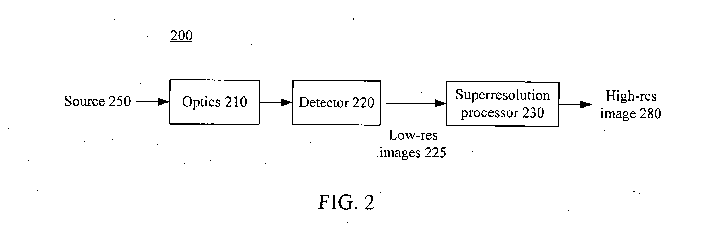
[0031]FIG. 2 is a block diagram of an electro-optic imaging system 200 according to the invention. The overall system 200 includes an optical subsystem 210, detector subsystem 220 and superresolution digital image processing subsystem 230. The image processing portion 230 has superresolution capability. The optical subsystem 210 and detector subsystem 220 produce lower resolution images 225 of a source 250, which are combined by the superresolution subsystem 230 to yield a higher resolution image 280 of the source.

[0032] In more detail, superresolution is the process of taking a collection of lower...


PUM


Abstract

A superresolution electro-optic imaging system operates in a manner that takes into account the different subsystems. For example, rather than designing the optical subsystem to be diffraction-limited, the optical subsystem can be designed in a manner that is better suited for subsequent superresolution processing and/or that reduces aliasing effects.

Description

BACKGROUND OF THE INVENTION [0001] 1. Field of the Invention [0002] This invention relates generally to superresolution electro-optic imaging systems, including the “end-to-end” design of such systems. [0003] 2. Description of the Related Art [0004] Electro-optic imaging systems typically include an optical subsystem (e.g., a lens assembly), an electronic detector subsystem (e.g., CCD detector array) and a digital image processing subsystem (e.g., typically implemented in dedicated chips or software). In most electro-optical imaging systems, the spatial sampling rate of the photodetector is well below the diffraction limit of the optical subsystem. In current technology, the smallest pixel dimensions (i.e., pixel-to-pixel pitch) are typically on the order of 3 to 4 microns. The corresponding Nyquist rate associated with such pixel dimensions are between 125 and 166 line pairs per millimeter (lp / mm). It is not uncommon to have optical subsystems with an F# as low as 3 or 4. Given tha...

Claims


Application Information

Patent Timeline
IPC IPC(8): H04N5/228
CPCH04N5/2254H04N3/1587H04N25/48H04N25/615
Inventor ROBINSON, M. DIRK
Owner RICOH KK
Why Eureka
Try Eureka