Dynamic random access memory and fabrication method thereof

Inactive Publication Date: 2007-11-22
UNITED MICROELECTRONICS CORP
View PDF4 Cites 6 Cited by
  • Summary
  • Abstract
  • Description
  • Claims
  • Application Information

AI Technical Summary

Benefits of technology

[0008]Accordingly, the present invention is directed to provide a DRAM having an isolation

Problems solved by technology

However, the isolation effect of the conventional isolation structure is not ideal becau

Method used


Image

  • Dynamic random access memory and fabrication method thereof
  • Dynamic random access memory and fabrication method thereof
  • Dynamic random access memory and fabrication method thereof

Examples


Example

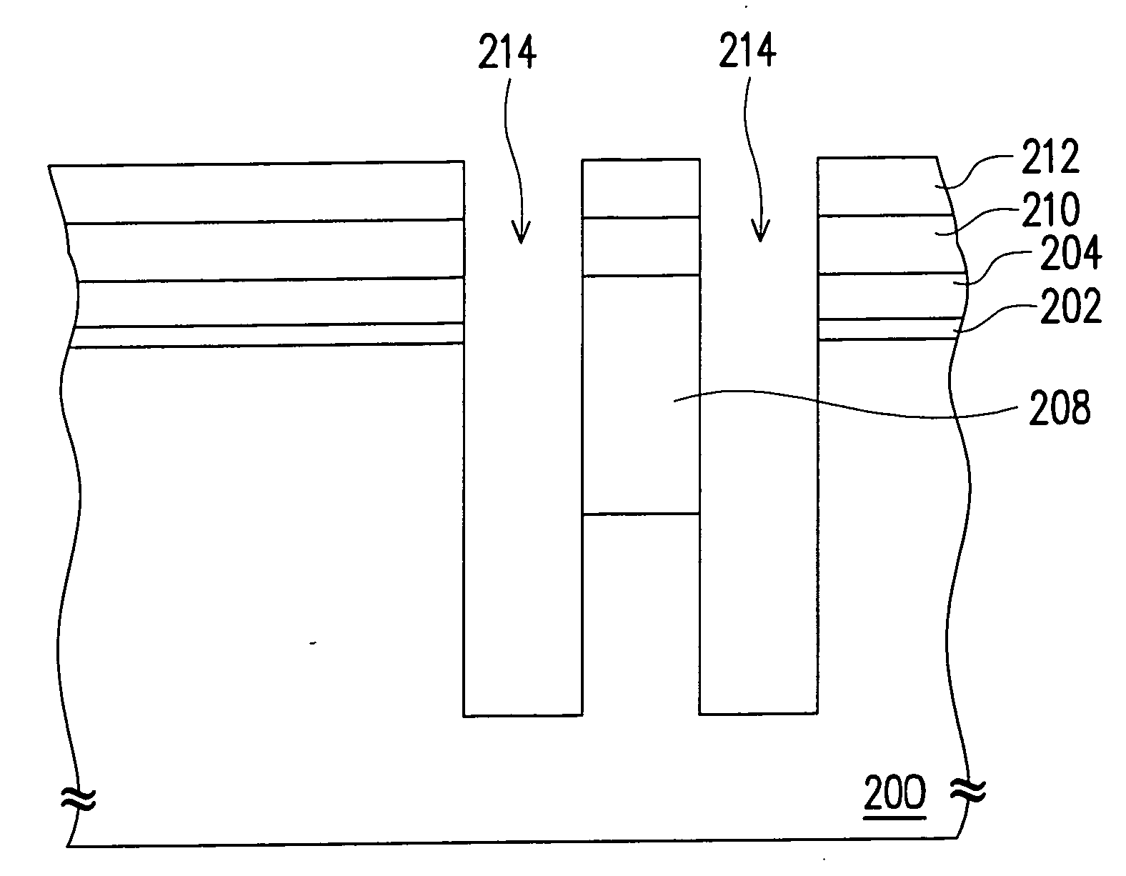
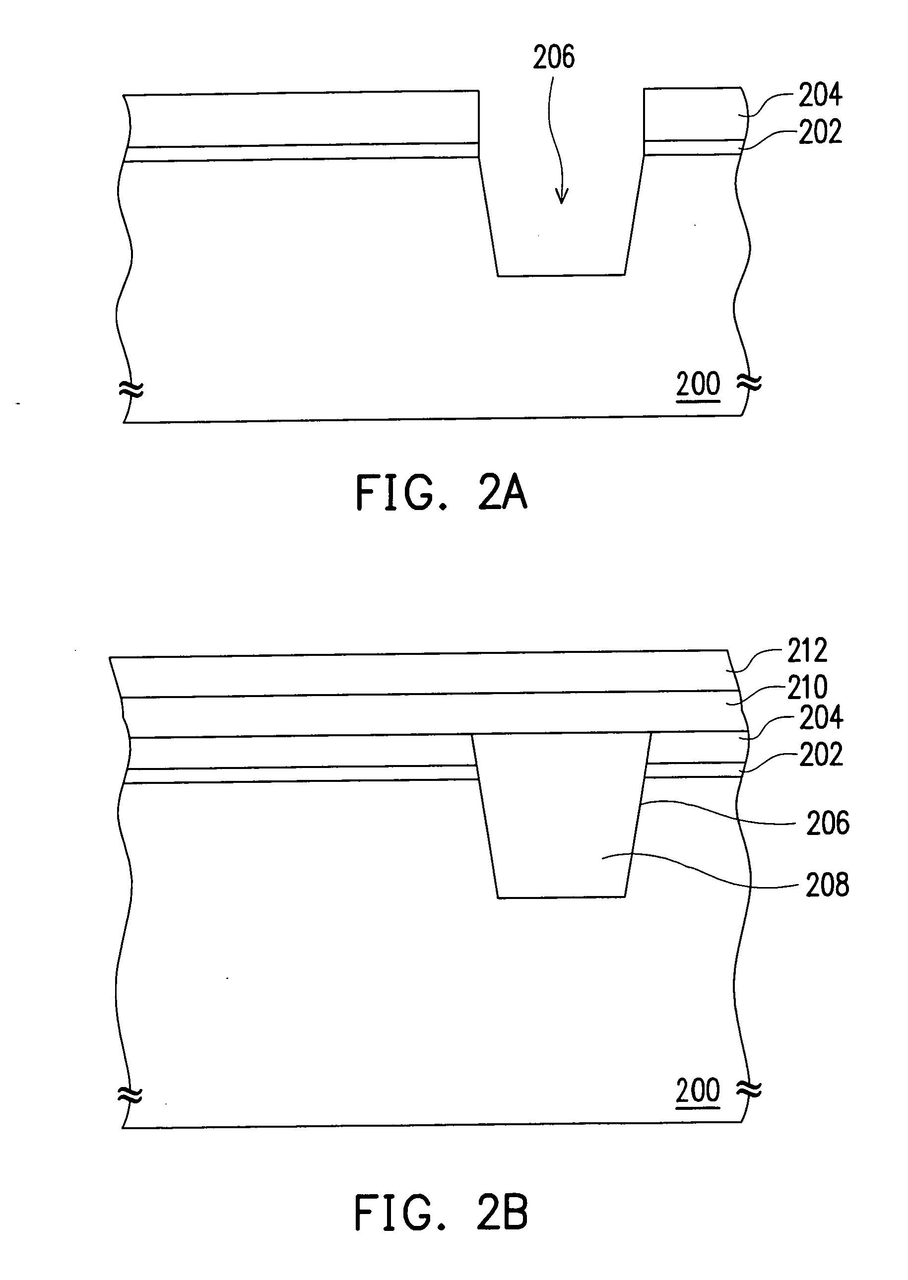
[0027]FIGS. 2A˜2H are cross-sectional views illustrating the fabricating process steps of a dynamic random access memory according to an embodiment of the present invention.

[0028]First, referring to FIG. 2A, a patterned pad oxide 202 and a patterned hard mask layer 204 are formed on the substrate 200 sequentially, and a portion of the substrate 200 is exposed. The substrate 200 is, for example, a silicon substrate. The material of the hard mask layer 204 is, for example, silicon nitride. Next, an etching process is performed to the substrate 200 using the hard mask layer 204 as the mask, to form a trench 206 in the substrate 200. The etching process performed to the substrate 200 is, for example, anisotropic etching process.

[0029]Then, referring to FIG. 2B, an insulation layer (not shown) is formed on the substrate 200 and the insulation layer fills up the trench 206. Next, a chemical mechanical polishing process is performed to the insulation layer by using the hard mask layer 204 ...


PUM


Abstract

A dynamic random access memory including a substrate, an isolation structure, two transistors, two trench capacitors and two passing gates is provided. The isolation structure, including a first isolation structure and a second isolation structure, is disposed in the substrate. The second isolation structure is disposed in the substrate above the first isolation structure and the bottom surface of the second isolation structure is lower than the top surface of the substrate. The periphery of the second isolation structure is beyond that of the first isolation structure. The transistors are disposed on the substrate respectively at two sides of the isolation structure. The trench capacitors are respectively disposed between the transistors and the isolation structures. A portion of the second isolation structure is disposed in the trench capacitor. The passing gates are completely disposed on the second isolation structure.

Description

BACKGROUND OF THE INVENTION[0001]1. Field of Invention[0002]The present invention relates to a dynamic random access memory (DRAM) and the fabrication method thereof. More particularly, the present invention relates to a DRAM with efficient isolation between the passing gates and the trench capacitors, and the fabrication method thereof.[0003]2. Description of Related Art[0004]Dynamic random access memory (DRAM) stores data with capacitors.[0005]The data of each memory cell is determined by the electric charge of the capacitor thereof. For the small-size memory cells, the surface area of the capacitor bottom electrode is increased to provide sufficient storage capacitance, so as to reduce the chance of data misjudgment and reduce the refresh frequency of data for better operation efficiency. To meet the requirements for the large surface area of the capacitor and the integration of the memory cell, the trench capacitor has become the most popular option.[0006]FIG. 1 is a cross-secti...

Claims


Application Information

Patent Timeline
IPC IPC(8): H01L21/8244
CPCH01L27/10861H10B12/038
Inventor WANG, CHIEN-KUOHUANG, JUN-CHILEE, RUEY-CHYRLIN, YUNG-CHANG
Owner UNITED MICROELECTRONICS CORP
Why Eureka
Try Eureka