
Dual balloon catheter and deployment of same

a dual-bladder catheter and catheter technology, applied in the field of catheters, can solve the problems of limiting blood flow and access to the side branch vessel, posing a higher risk of side branch vessel entrapment, and difficult to pass a wire through the stent structure for treating the other vessel, so as to minimize the flow problem, minimize the effect of stent flow reduction and easy insertion

Inactive Publication Date: 2007-11-22
ABBOTT LAB INC
View PDF2 Cites 24 Cited by
  • Summary
  • Abstract
  • Description
  • Claims
  • Application Information

AI Technical Summary

Benefits of technology

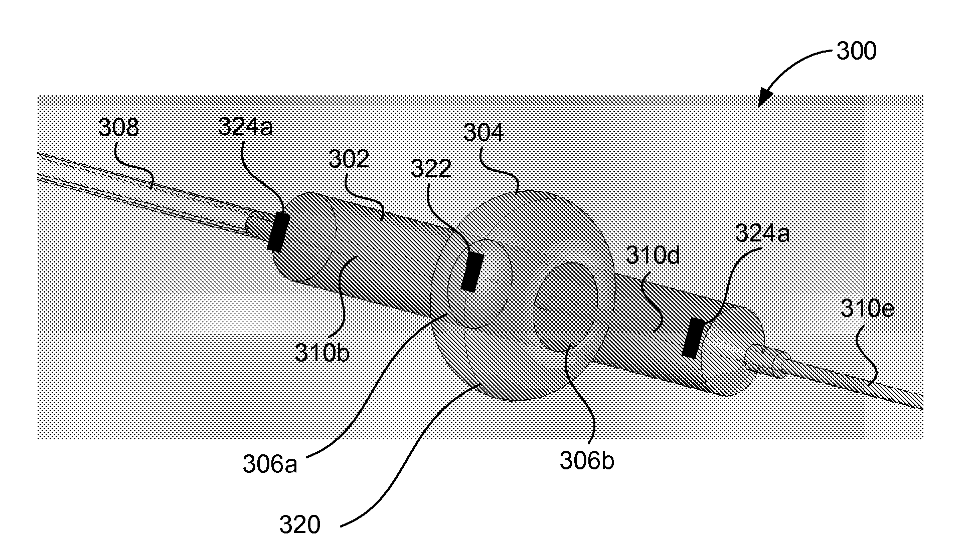
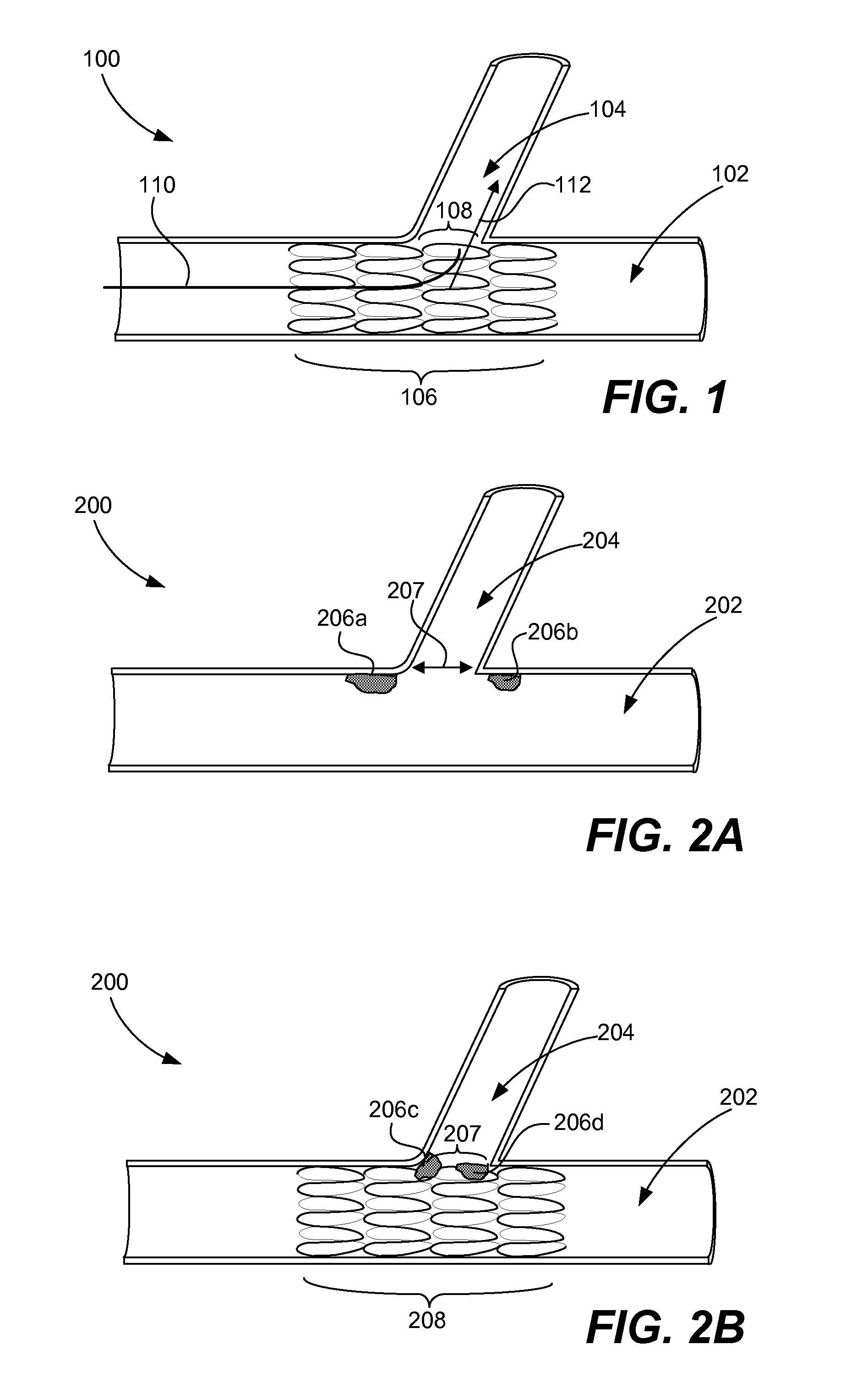
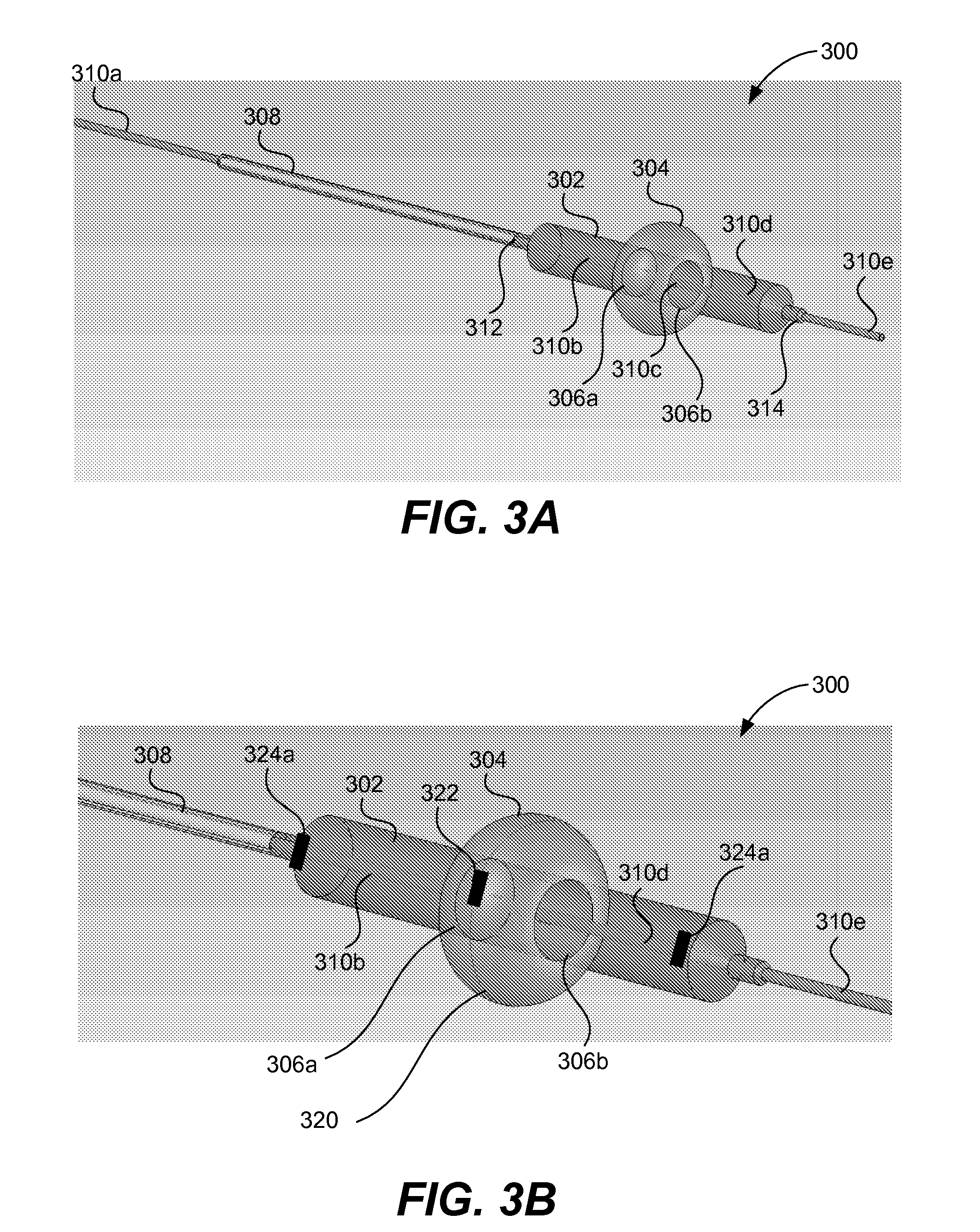
[0009] Accordingly, catheter apparatus and methods for deploying a stent in a bifurcated vessel while minimizing flow problems in the branch vessel are provided. In general, the catheter includes at least one non-compliant inflation structure for pushing a stent against a vessel wall in a main vessel and a compliant inflation structure for forming an opening in the stent across an opening in a branch vessel. Ideally, flow reduction caused by the stent is minimized due to the stent opening at the branch vessel. Additionally, other medical devices, such as a guide wire or a second stent, may be easily inserted through the opening in the stent into the branch vessel.

Problems solved by technology

Insertion of a stent into a main vessel spanning the bifurcation point may pose a limitation to blood flow and access to the side branch vessel.
In this regard, the tubular slotted hinged design of the Palmaz-Schatz intracoronary stent, in particular, is felt to be unfavorable for lesions with a large side branch and is generally believed to pose a higher risk of side branch vessel entrapment where the stent prevents or limits access to the side branch.
In situations where the main or side branch has been stented and the stent is positioned over the bifurcation, it may be difficult to pass a wire through the stent structure for treating the other vessel, if desired.

Method used


Image

  • Dual balloon catheter and deployment of same
  • Dual balloon catheter and deployment of same
  • Dual balloon catheter and deployment of same

Examples


Embodiment Construction

[0033] Reference will now be made in detail to a specific embodiment of the invention. An example of this embodiment is illustrated in the accompanying drawings. While the invention will be described in conjunction with this specific embodiment, it will be understood that it is not intended to limit the invention to one embodiment. On the contrary, it is intended to cover alternatives, modifications, and equivalents as may be included within the spirit and scope of the invention as defined by the appended claims. In the following description, numerous specific details are set forth in order to provide a thorough understanding of the present invention. The present invention may be practiced without some or all of these specific details. In other instances, well known process operations have not been described in detail in order not to unnecessarily obscure the present invention.

[0034] In general, a dual balloon catheter for use in a bifurcated body vessel is provided. The catheter i...


PUM


Abstract

Disclosed are catheter apparatus and methods for deploying a stent in a bifurcated vessel while minimizing flow problems in the branch vessel. In general, the catheter includes at least one non-compliant inflation structure for pushing a stent against a vessel wall in a main vessel and a compliant inflation structure for forming an opening in the stent across an opening in a branch vessel. Ideally, flow reduction caused by the stent is minimized due to the stent opening at the branch vessel. Additionally, other medical devices, such as a guide wire or a second stent, may be easily inserted through the opening in the stent into the branch vessel.

Description

CROSS REFERENCE TO RELATED PATENT APPLICATION [0001] This application claims priority of co-pending U.S. Provisional Patent Application No. 60 / 802,010, entitled DUAL BALLOON CATHETER AND DEPLOYMENT OF SAME, by Richard R Newhauser, filed 18 May 2006, under 35 U.S.C. §119(e), and which application is incorporated herein by reference in its entirety for all purposes.BACKGROUND OF THE INVENTION [0002] The present invention relates generally to catheters. More particularly, the present invention relates to catheters that are positioned in the vicinity of vessel bifurcations. [0003] A type of endoprosthesis device, commonly referred to as a stent, may be placed or implanted within a vein, artery or other tubular body organ for treating occlusions, stenoses, or aneurysms of a vessel by reinforcing the wall of the vessel or by expanding the vessel. Stents have been used to treat dissections in blood vessel walls caused by balloon angioplasty of the coronary arteries as well as peripheral ar...

Claims


Application Information

Patent Timeline
IPC IPC(8): A61F2/84
CPCA61F2/856A61F2/954A61F2/958A61M2025/1045A61M25/0032A61M25/1011A61M2025/1013A61F2250/0039
Inventor NEWHAUSER, RICHARD R.HUANG, HOWARD H.
Owner ABBOTT LAB INC
Learn More