Bioabsorbable stents with reinforced filaments

a technology of bioabsorbable stents and reinforced filaments, which is applied in the field of bioabsorbable stents with reinforced filaments, can solve the problems of mechanical strength and physical limitations of as-processed bioabsorbable materials, and achieve the effect of improving the material properties of stents

Active Publication Date: 2007-11-22
BOSTON SCI SCIMED INC
View PDF22 Cites 64 Cited by
  • Summary
  • Abstract
  • Description
  • Claims
  • Application Information

AI Technical Summary

Benefits of technology

[0003]The present invention describes a novel way to enhance the mate

Problems solved by technology

Key limitations of bioabsorbable stents are the physical limitations of the as-p

Method used


Image

  • Bioabsorbable stents with reinforced filaments
  • Bioabsorbable stents with reinforced filaments
  • Bioabsorbable stents with reinforced filaments

Examples


Embodiment Construction

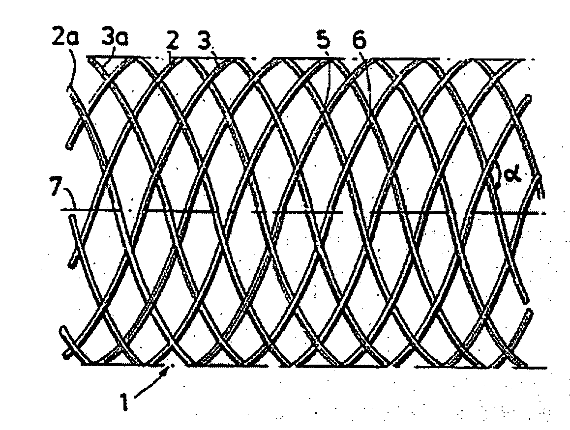
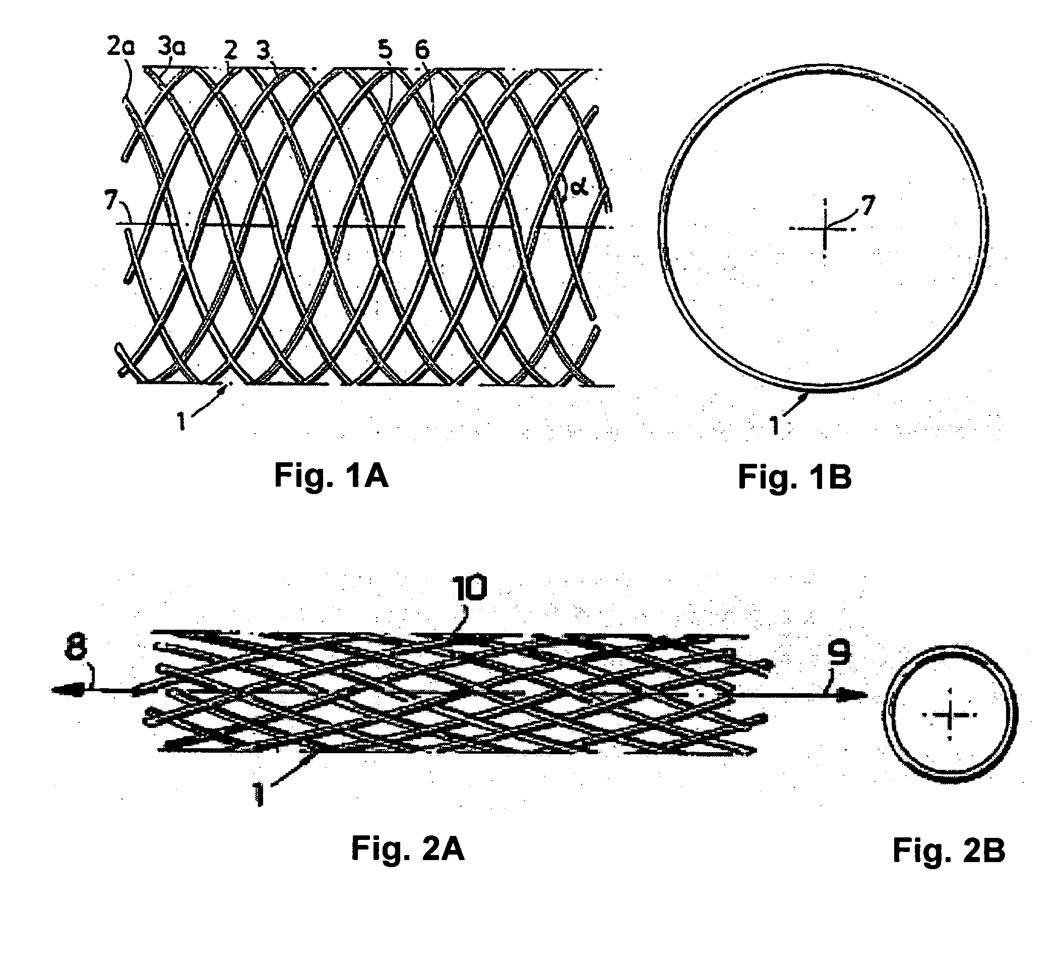
[0013]The present invention is directed to stents that are bioabsorbed by a patient upon implantation or insertion of the stent into the patient. The stents of the present invention are adapted for deployment at various placement sites within the patient, and include vascular stents (e.g., coronary vascular stents and peripheral vascular stents such as cerebral stents), urinary stents (e.g., urethral stents and ureteral stents), biliary stents, tracheal stents, gastrointestinal stents and esophageal stents.

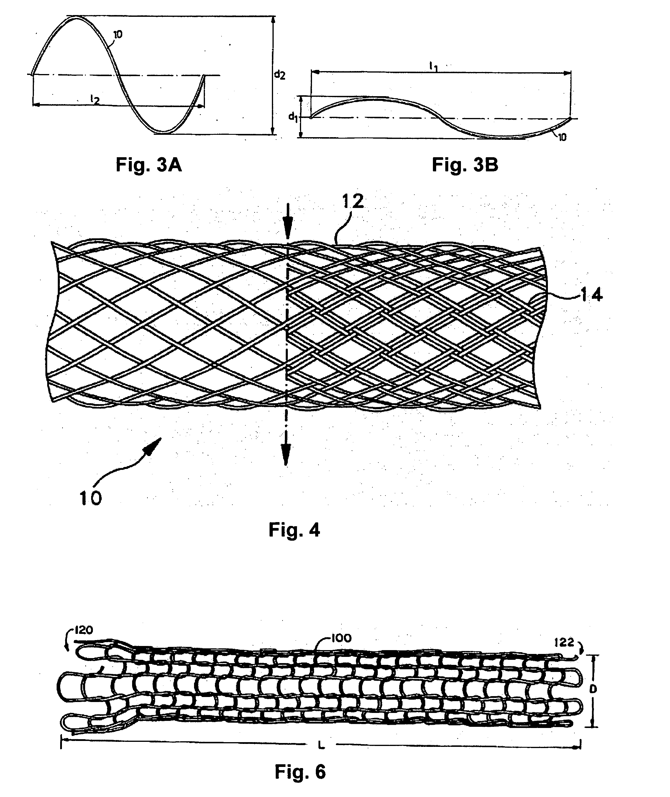
[0014]The stents of the present invention contain one or more filaments (also referred to herein as “oriented filaments”), which in turn contain an oriented bioabsorbable polymeric material (also referred to herein as “oriented material”). The polymer molecules within the oriented bioabsorbable polymeric material have a helical orientation with an axis that is which is aligned with respect to (e.g., the axes of the helices are parallel to) the longitudinal axis of the filament. As...


PUM

PropertyMeasurementUnit
Fractionaaaaaaaaaa
Fractionaaaaaaaaaa
Temperatureaaaaaaaaaa

Abstract

According to an aspect of the present invention, a stent is provided, which contains at least one filament that has a longitudinal axis and comprises a bioabsorbable polymeric material. Polymer molecules within the bioabsorbable polymeric material are provided with a helical orientation which is aligned with respect to the longitudinal axis of the filament. The stent is at least partially bioabsorbed by a patient upon implantation or insertion of the stent into the patient.

Description

BACKGROUND OF THE INVENTION[0001]Bioabsorbable stents are a key development focus for many medical device companies because they are expected to eliminate many of the long-term issues that may arise from the use of biostable stents.[0002]Key limitations of bioabsorbable stents are the physical limitations of the as-processed bioabsorbable materials, including the mechanical strength or the same. The mechanical properties of bioabsorbable materials have been enhanced previously by utilizing a process that is commonly referred to as “self reinforcement” or “orientrusion” wherein the material is drawn in a manner such that the polymer strands within the filament become aligned with the axis of the filament. Such processes are known to produce tensile modulus of approximately 2 GPa to 8 GPa for materials such as polymers and copolymers of polylactide (PLA), including poly-L-lactide (PLLA), poly-D-lactide (PDLA), poly-DL-lactide (PDLLA).SUMMARY OF THE INVENTION[0003]The present invention...

Claims


Application Information

Patent Timeline
IPC IPC(8): A61F2/06A61F2/90
CPCA61F2/90A61F2210/0004A61L31/06A61L31/16A61L31/148A61L31/022C08L67/04
Inventor HEADLEY, F. ANTHONYGEITZ, KURT
Owner BOSTON SCI SCIMED INC
Why Eureka
Try Eureka