Cryogenic system

a cryogenic system and cryogenic technology, applied in the field of cryogenic systems, can solve the problems of increasing the operation cost of the system, affecting the operationability of the cryogenic system, and the maintenance time cannot be shortened to a few hours, and achieve excellent thermal contact

Active Publication Date: 2007-11-29
KOBE STEEL LTD
View PDF11 Cites 31 Cited by
  • Summary
  • Abstract
  • Description
  • Claims
  • Application Information

AI Technical Summary

Benefits of technology

[0032] In consideration of these situations, an object of the present invention is to provide a cryogenic system that reproducibly achieves excellent thermal contact at a cooling stage without applying a large stress to a cryocooler unit structure.

Problems solved by technology

This increases the operation cost of the system.
Thus, the maintenance cannot be shortened to a few hours.
The second problem in the maintenance of the cryogenic system relates to thermal resistance between the cryocooler unit 51 and an element to be cooled.
This considerably impairs the operationability of the cryogenic system.
Increased thermal resistance between the cryocooler unit and an element to be cooled partly results from contamination in the cryocooler sleeve 60.
As a result, this decreases the contact area at the interface between the first cooling stage 57 and the radiation-shield 56, increases the thermal resistance, and may cause the same problem as described above.
However, in the technique described in U.S. Pat. No. 5,918,470, to make effective use of the gasket to decrease the thermal resistance, very high pressure must be applied to pinch the gasket.
This may damage the cryocooler unit even with a soft metal gasket like indium.
Thus, the cryocooler unit may be damaged by a large mechanical stress.
On the contrary, an insufficient mechanical stress results in a large thermal resistance.
Thus, it is very difficult to adjust the mounting position of the cryocooler unit so that the mechanical stress would not be too large and not too small.
Thus, it may take many hours to resume the operation.
In addition, replacement of the gasket after removing the cryocooler unit takes additional time for maintenance.
This results in a larger difference in temperature and therefore lower efficiency than the thermal transfer via a solid.
Furthermore, both techniques described in U.S. Pat. No. 5,918,470 and U.S. Pat. No. 6,164,077 cannot solve the problem of contamination in the cryocooler sleeve.

Method used


Image

  • Cryogenic system
  • Cryogenic system
  • Cryogenic system

Examples


Embodiment Construction

[0067] Embodiments according to the present invention will now be described with reference to the drawings.

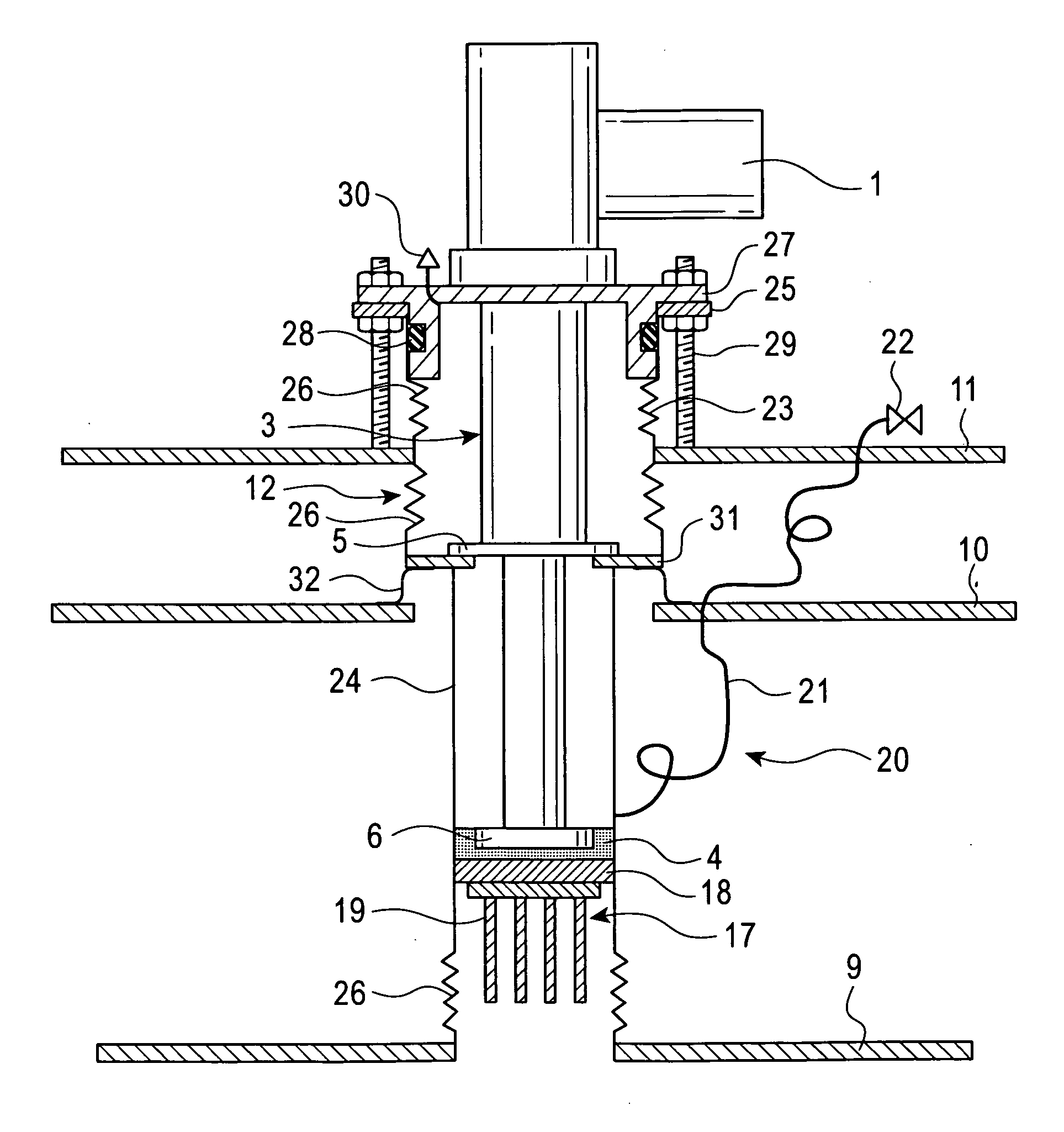
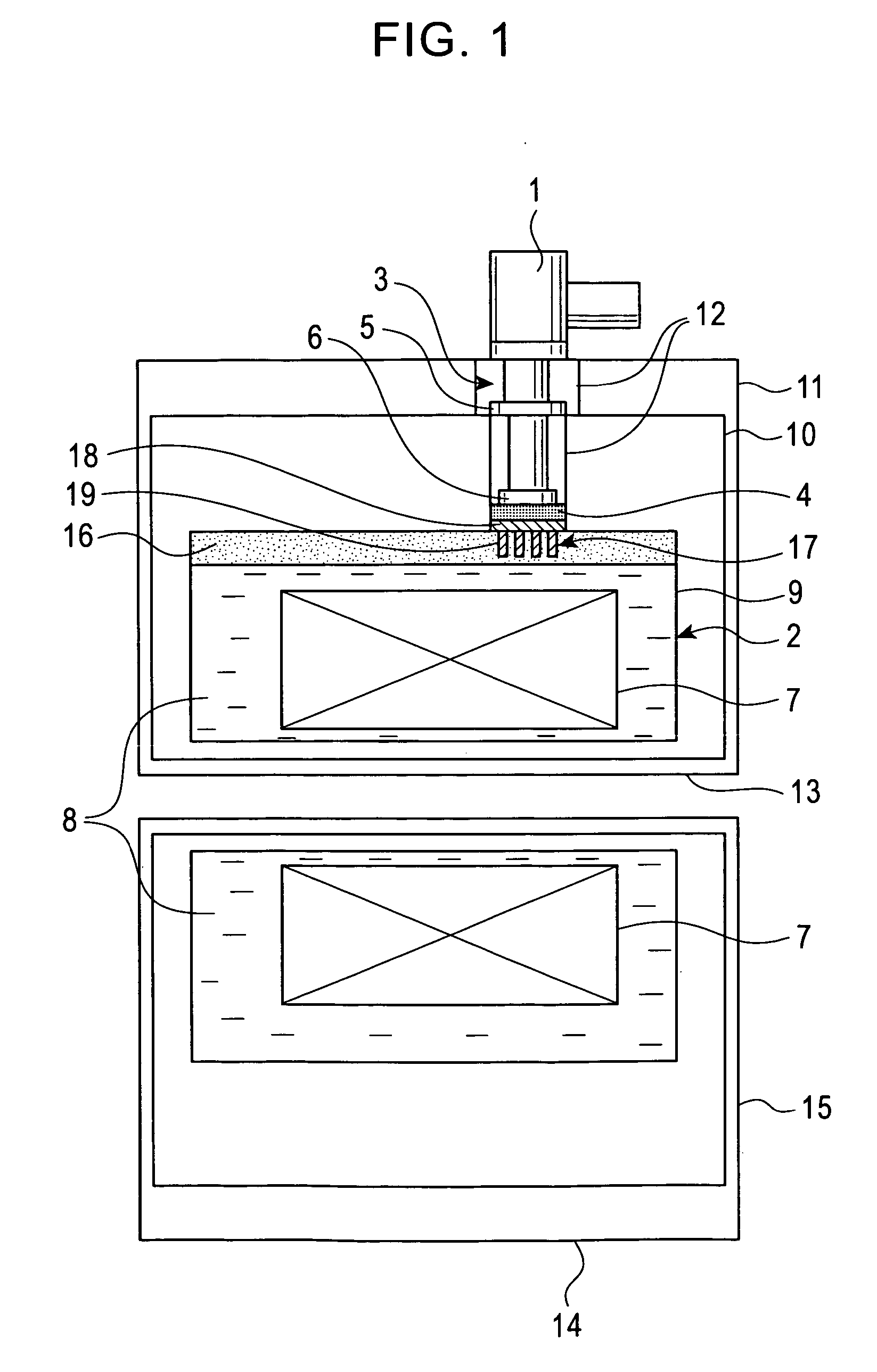
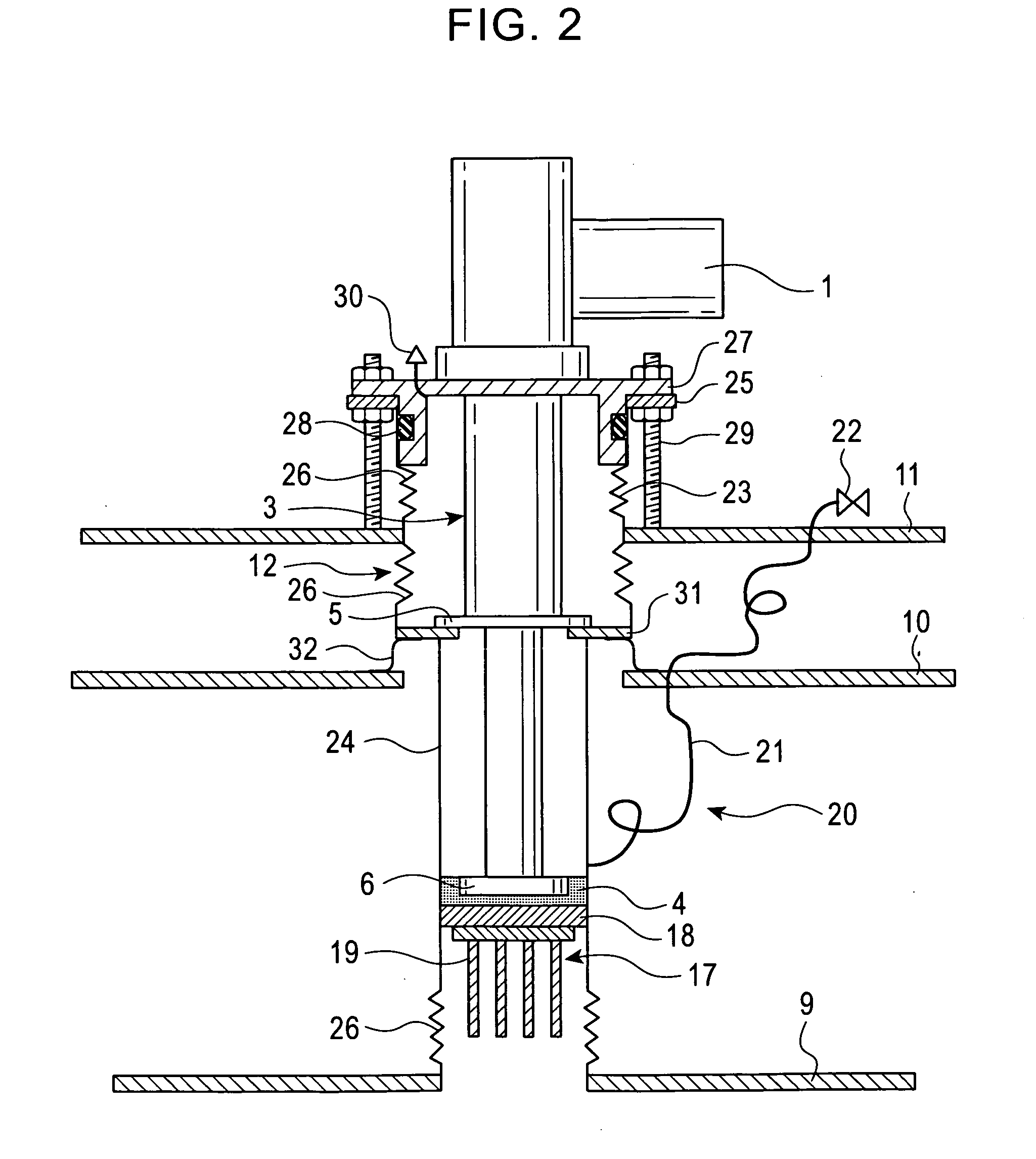
[0068]FIG. 1 is a schematic sectional view of one example of a cryogenic system, MRI. This cryogenic system includes a cryocooler unit 1 and an element to be cooled 2. The cryocooler unit 1 includes a cooling stage 3. A space is formed between the cooling stage 3 and the element to be cooled 2, and a thermal joint 4 is placed in the space. The thermal joint 4 is composed of a substance that has the melting point higher than the cooling temperature of the element to be cooled 2 and that is in a liquid or gaseous state at room temperature and atmospheric pressure. The thermal switch of the thermal joint 4 is on in a solid state.

[0069] The exemplary cooling stage 3 includes a first cooling stage 5 and a second cooling stage 6 in series. The second cooling stage 6 has a temperature of about 4K, which is lower than that of the first cooling stage 5. The second cooling stage6 has a...


PUM

PropertyMeasurementUnit
temperatureaaaaaaaaaa

Abstract

A cryogenic system includes a space formed between a cooling stage of a cryocooler unit and an element to be cooled, and a thermal joint placed in the space, wherein the thermal joint is composed of a substance that has a melting point higher than the cooling temperature of the element to be cooled and that is in a liquid or gaseous state at room temperature and atmospheric pressure. The cryogenic system can achieve reproducible and excellent thermal contact at a cooling stage without applying a large mechanical stress to a cryocooler unit structure.

Description

BACKGROUND OF THE INVENTION [0001] 1. Field of the Invention [0002] The present invention relates to a cryogenic system for cooling a superconducting magnet or the like. [0003] 2. Description of the Related Art [0004] It is well known that a superconducting magnet apparatus must be kept at cryogenic temperatures to maintain the superconductivity. Examples of cooling means include a method of immersing the superconducting magnet in a cryogen, such as liquid helium, and a method for cooling the superconducting magnet directly with a cryocooler without using a cryogen. [0005]FIG. 13 shows a structure of a conventional cryogenic system. This is magnetic resonance imaging (MRI), which is known as a medical apparatus. FIG. 13 is a longitudinal section of the cryogenic system housing a superconducting solenoid magnet having a horizontal central axis. [0006] This cryogenic system includes a cryocooler unit 51, a vacuum chamber 52, a superconducting magnet 53, a liquid helium bath 55, and a ...

Claims


Application Information

Patent Timeline
Patent Type & Authority Applications(United States)
IPC IPC(8): F25B19/00F25B9/00G01R33/3815A61B5/055F25D19/00H01F6/04H01L39/04
CPCC01B3/0089F25B2400/17F28F2013/008Y02E60/324F25D19/006Y02E60/32
Inventor MIKI, TAKASHI
Owner KOBE STEEL LTD
Why Eureka
Try Eureka