Shower Head and Film-Forming Device Using the Same

a technology of film-forming device and shower head, which is applied in the direction of coating, chemical vapor deposition coating, metallic material coating process, etc., can solve the problems of film deposition reaction undetected, formation of particles, and unwanted film ranging from several millimeters to several centimeters in diameter, etc., and achieve the effect of solving

Active Publication Date: 2007-11-29
TOKYO ELECTRON LTD
View PDF24 Cites 97 Cited by
  • Summary
  • Abstract
  • Description
  • Claims
  • Application Information

AI Technical Summary

Benefits of technology

[0005] Taking account of this disadvantage, the present invention has been made to effectively solve the same. The object of the present invention is to provide a showerhead tha

Problems solved by technology

If a source gas with a relatively low steam pressure and a relatively high activation energy is mixed with a supporting gas while the source gas is being fed, a film deposition reaction undesirably occurs.
However, in the course of repeatedly performing a film deposition process on the wafer, there has been a case in which an unwanted film ranging from several millimeters to several centimeters in diameter is deposited around source-gas jetting orifices, which are formed in a gas jettin

Method used


Image

  • Shower Head and Film-Forming Device Using the Same
  • Shower Head and Film-Forming Device Using the Same
  • Shower Head and Film-Forming Device Using the Same

Examples


first embodiment

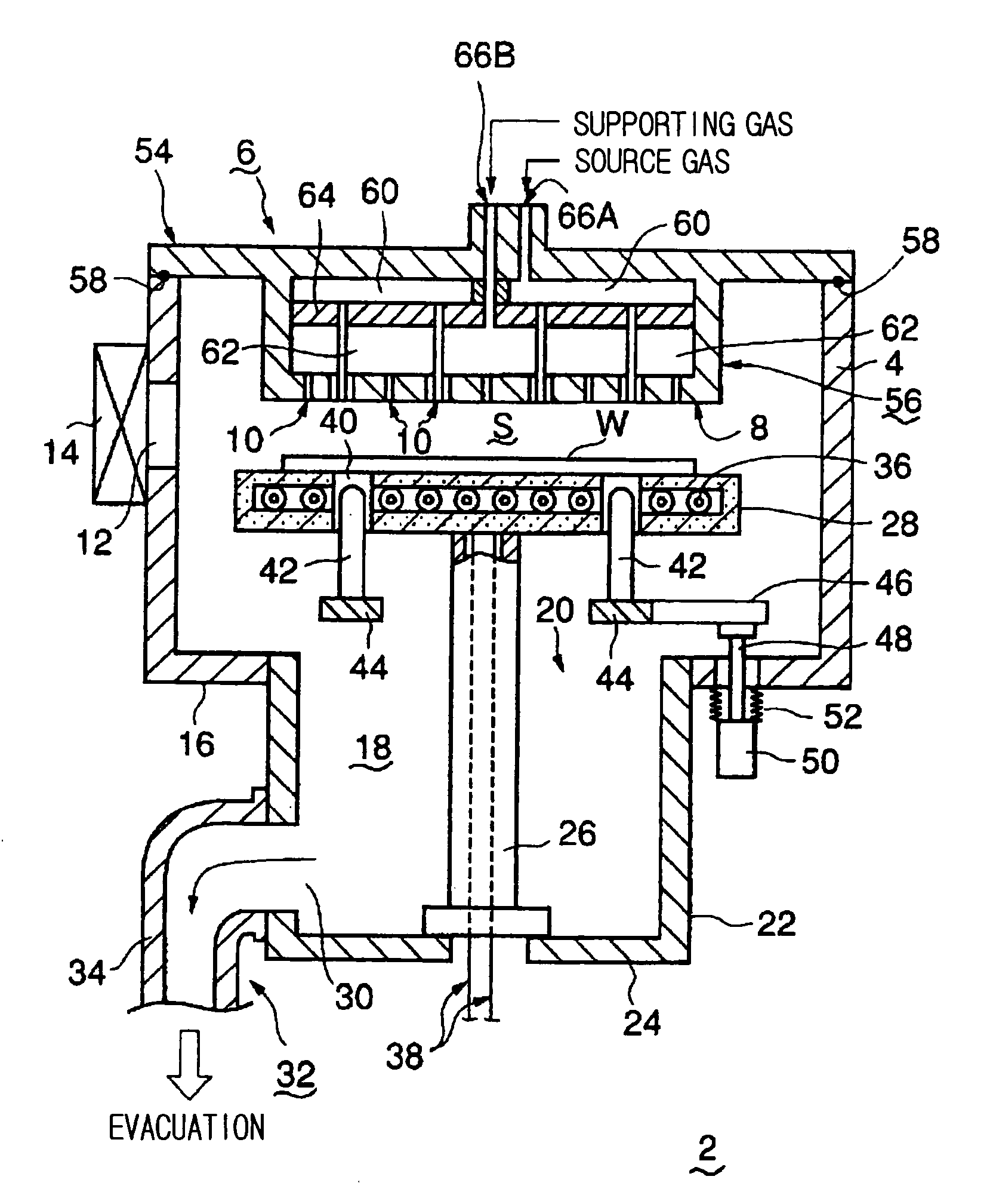
[0032] With reference to FIGS. 1 to 4, a first embodiment of the present invention is described.

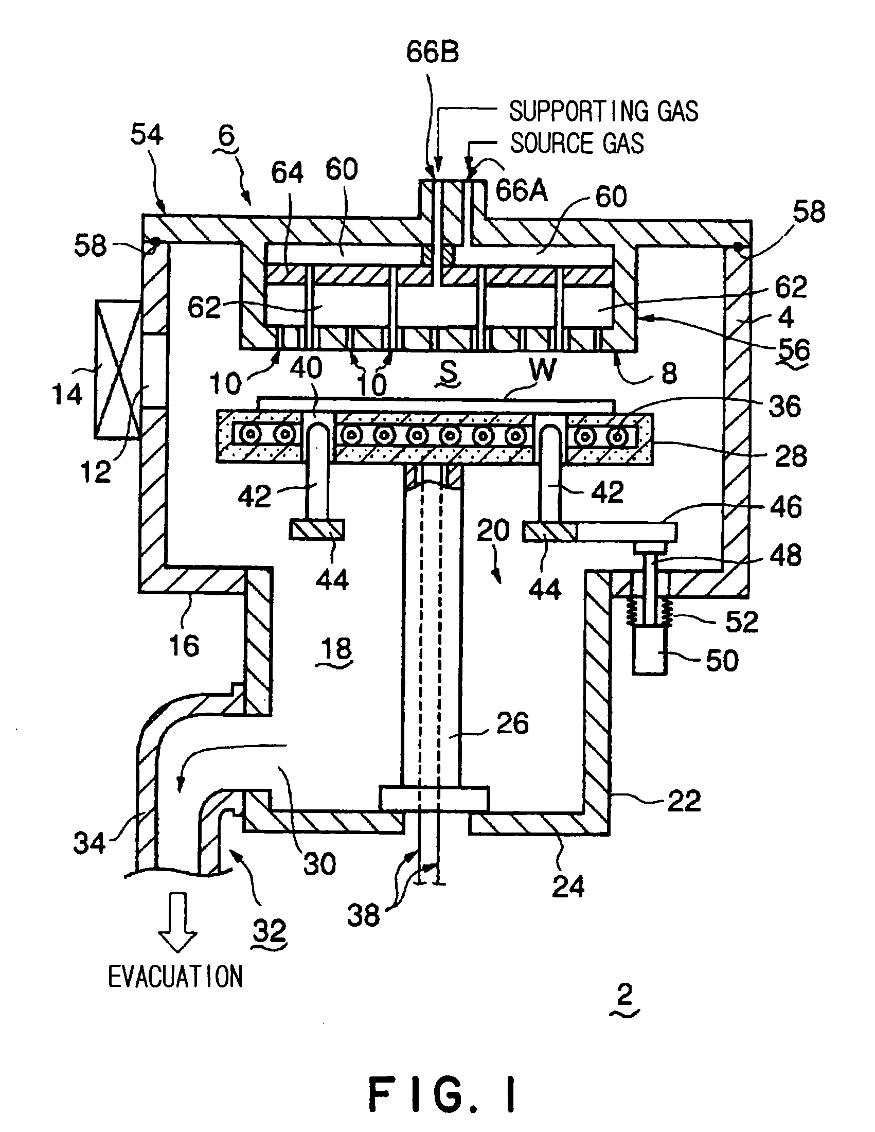
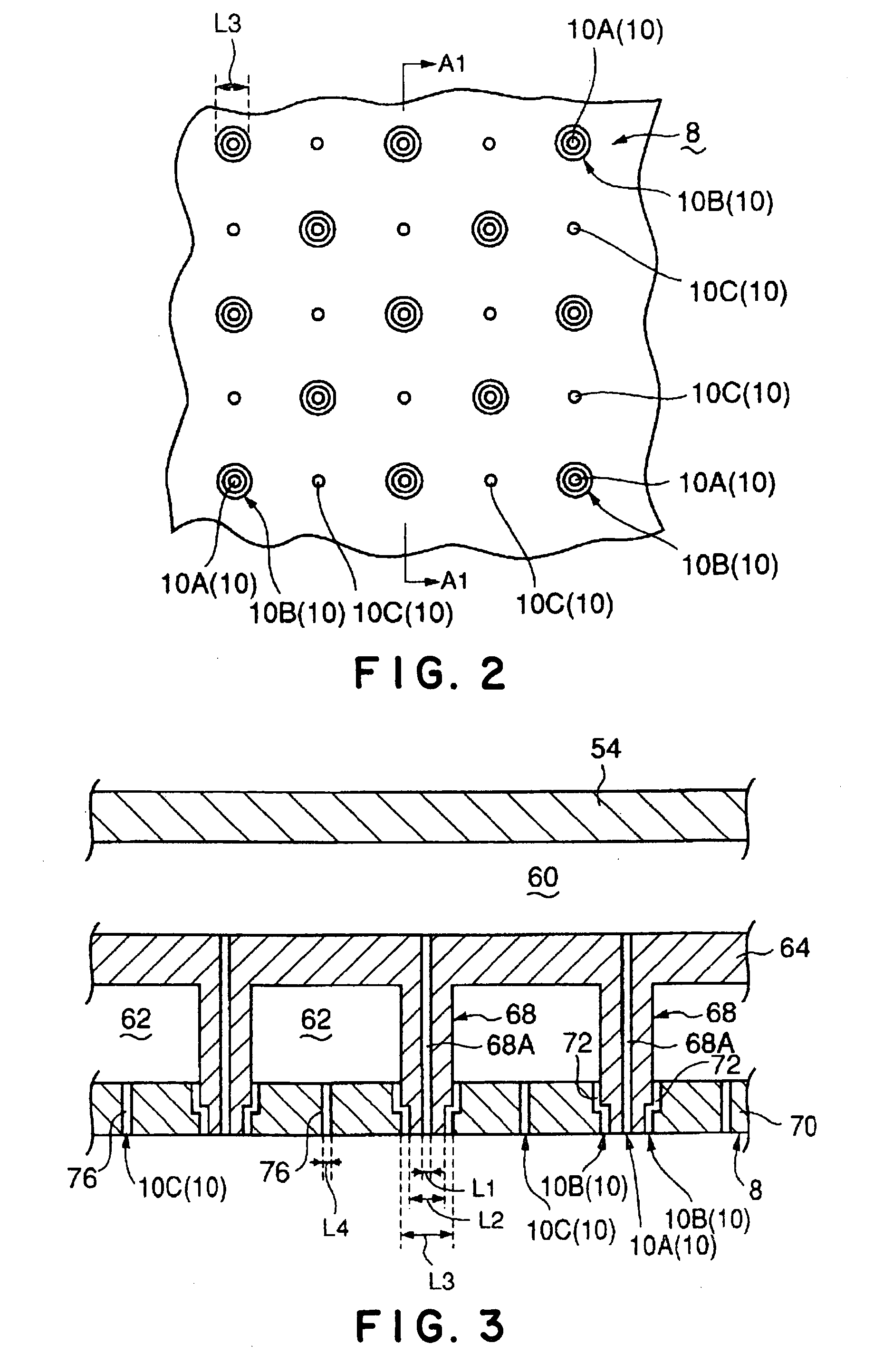
[0033] A film deposition apparatus 2 shown in FIG. 1 includes a cylindrical processing vessel 4 made of, e.g., aluminum. A showerhead 6 that supplies a source gas and a supporting gas for depositing a film is provided on a top part in the processing vessel 4. The showerhead 6 is adapted to jet the gases toward a processing space S in the processing vessel 4 through a plurality of gas jetting orifices 10 formed in a gas jetting surface 8. Details of the showerhead 6 is described hereafter.

[0034] A loading / unloading port 12 is formed in a sidewall of the processing vessel 4, through which a semiconductor wafer W as an object to be processed is loaded into the processing vessel 4 and unloaded therefrom. A gate vale 14 capable of being hermetically opened and closed is disposed on the loading / unloading port 12.

[0035] An evacuation chamber 18 is formed below the processing vessel 4. The eva...

second embodiment

[0058] A second embodiment of the present invention is described with reference to FIGS. 6 and 7.

[0059] As shown in FIGS. 6 and 7 illustrating this embodiment, instead of the first supporting-gas jetting orifices 10B of a ring shape, a plurality of first supporting-gas jetting orifices 10D each having a circular shape are formed to adjacently surround respective source-gas jetting orifices 10A.

[0060] In an example shown in FIG. 6, four first supporting-gas jetting orifices 10D are arranged around one source-gas jetting orifice 10A at 90° intervals about the orifice 10A. A combination of one source-gas jetting orifice 10A and four first supporting-gas jetting orifices 10D forms a jetting orifice unit 80. Although the number of the first supporting-gas jetting orifices 10D relative to one source-gas jetting orifice 10A is not limited to four, it is preferable that two or more first supporting-gas jetting orifices 10D are arranged at equally spaced intervals, in order to surround a s...


PUM

PropertyMeasurementUnit
Currentaaaaaaaaaa
Digital informationaaaaaaaaaa
Melting pointaaaaaaaaaa

Abstract

The present invention relates to a showerhead that supplies a source gas and a supporting gas for depositing a film into a processing vessel of a film deposition apparatus. The showerhead includes a body which is provided with a gas jetting surface (8). In the showerhead body, there are defined a first diffusion chamber (60) that receives the source gas and diffuses the same, and a second diffusion chamber (62) that receives the supporting gas and diffuses the same. The gas jetting surface has source-gas jetting orifices (10A) that are in communication with the first diffusion chamber, and first supporting-gas jetting orifices (10B) that are in communication with the second diffusion chamber. Each of the first supporting-gas jetting orifices (10B) are formed into a ring shape that adjacently surrounds a corresponding one of the source-gas jetting orifices (10A).

Description

TECHNICAL FIELD [0001] The present invention relates to a showerhead for use in supplying a gas into a processing vessel to deposit a film on a surface of an object to be processed such as a semiconductor wafer, and to a film deposition apparatus using such a showerhead. BACKGROUND ART [0002] In manufacturing a semiconductor integrated circuit, an object to be processed such as a semiconductor wafer is generally, repeatedly subjected to various single-wafer processes, such as a film deposition process, etching process, heat process, modification process, and crystallization process, so as to form a desired integrated circuit. In order to perform these processes, a process gas fit for the kind of process in question is supplied into a processing vessel. In a film deposition process, a source gas and a supporting gas, such as an oxidation gas and a reduction gas, are supplied into a processing vessel capable of forming a vacuum, from a showerhead disposed on a top part of the processi...

Claims


Application Information

Patent Timeline
IPC IPC(8): H01L21/31C23C16/455
CPCC23C16/45565
Inventor AMIKURA, MANABUIWATA, TERUO
Owner TOKYO ELECTRON LTD
Why Eureka
Try Eureka