Light Source with Electron Cyclotron Resonance

a light source and electron cyclotron technology, applied in the field of light sources, can solve the problems of limited lifetime, low light efficacy and/or present high cost, limit the lifetime of light sources, etc., and achieve the effect of strong light intensity and high efficacy

Inactive Publication Date: 2007-11-29
SORTAIS PASCAL +1
View PDF4 Cites 13 Cited by
  • Summary
  • Abstract
  • Description
  • Claims
  • Application Information

AI Technical Summary

Benefits of technology

[0009] The object of the invention is to remedy these shortcomings and, in particular to provide an electrode-free l

Problems solved by technology

However known sources often have a low light efficacy and/or present high costs due to a limited lifetime.
The wear of the electrodes, due to bomba

Method used


Image

  • Light Source with Electron Cyclotron Resonance
  • Light Source with Electron Cyclotron Resonance
  • Light Source with Electron Cyclotron Resonance

Examples


Embodiment Construction

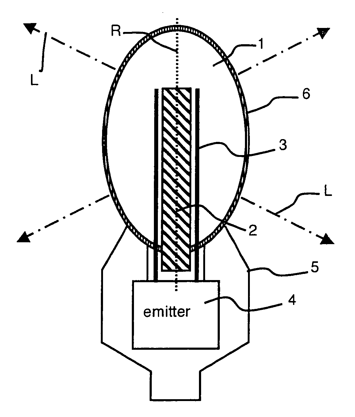
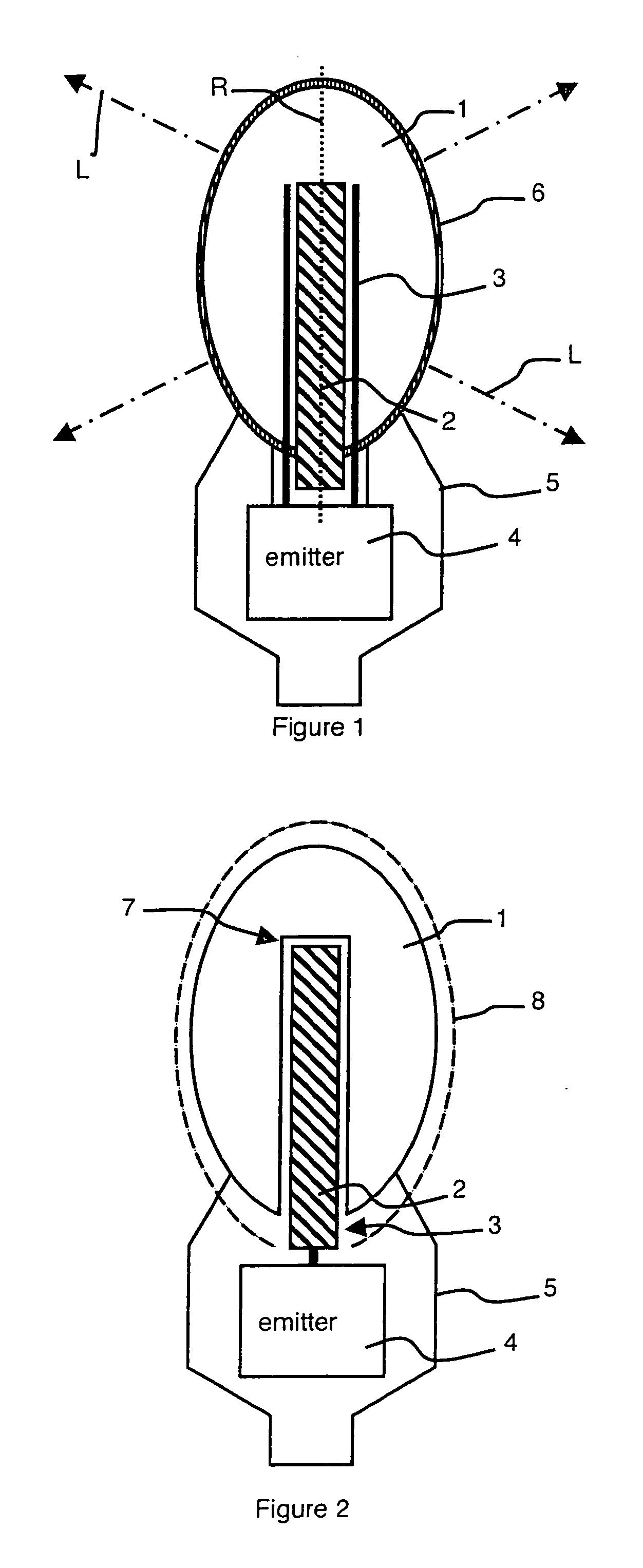
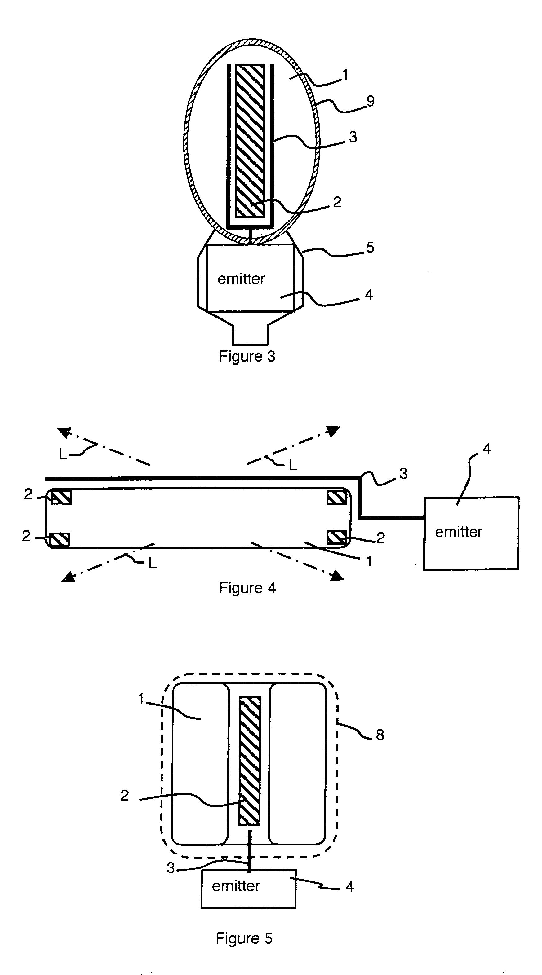
[0014] The light source represented in FIG. 1 comprises a sealed chamber 1 substantially in the form of a bulb, having an external wall transparent to light. The chamber 1 contains a gas at low pressure, for example one or more rare gases at a total pressure of 2 μbar, deuterium or a metal vapor, for example sodium, zinc or mercury. When the gas is a mercury vapor, the pressure in the chamber 1 can be the pressure of mercury vapor at room temperature which is about 2 μbar. The wall of the chamber 1 can be transparent only in a required spectral band, for example in a visible band or in a UV band. Typically, the materials used for the light sources have a cut-off wavelength situated in the UV band of the electromagnetic spectrum, for example at 150 nm.

[0015] In FIG. 1, a single permanent magnet 2 and an antenna 3 connected to an emitter 4 penetrate into the chamber 1 in hermetically sealed manner. The permanent magnet 2 and the antenna 3 are then arranged partly inside the chamber1 ...


PUM


Abstract

The light source comprises an emitter (4) which, by means of at least one antenna (3), creates an ultra high-frequency electromagnetic wave in a sealed chamber (1) and which provides the lamp with power. The chamber (1) has a wall that is transparent to light and contains a gas at low pressure. A permanent magnet (2) creates a static magnetic field inside the chamber (1). The respective values of the static magnetic field and of the frequency of the electromagnetic wave are determined such as to cause an electron cyclotron resonance inside the chamber (1). The emitter (4), antenna (3) and magnet (2) are disposed in relation to the chamber (1) in such a way as to free a solid angle of at least 2π steradians for the light. The antenna (3) can be disposed inside the chamber (1) and can, optionally, be formed by the magnet (2). The magnet is substantially enveloped by the chamber (1).

Description

BACKGROUND OF THE INVENTION [0001] The invention relates to a light source supplied by ultra-high frequency, comprising an emitter which, by means of at least one antenna, creates an ultra high-frequency electromagnetic wave in a sealed chamber having a wall transparent to light and containing a gas at low pressure, the source comprising magnetic means designed to create a static magnetic field inside the chamber, the respective values of the static magnetic field and of the frequency of the electromagnetic wave being predetermined in such a way as to cause an electron cyclotron resonance inside the chamber. STATE OF THE ART [0002] Visible or ultraviolet (UV) light sources supplied by ultra-high frequency conventionally comprise an emitter creating an ultra high-frequency electromagnetic wave in a sealed chamber that is transparent to light and contains a gas at low pressure. The gas can be ionized and the electrons accelerated by means of an ultra high-frequency discharge. The ener...

Claims


Application Information

Patent Timeline
IPC IPC(8): H05H13/00F21K99/00H01J65/04
CPCH01J65/044H01J65/042
Inventor SORTAIS, PASCALPELLET, XAVIER
Owner SORTAIS PASCAL
Why Eureka
Try Eureka