Methods and systems providing an adaptive threshold for a beam sharpened pulse radar

a pulse radar and adaptive threshold technology, applied in the field of pulse radar operation, can solve the problems of inability to adjust the filter such that the upper pass-band edge corresponds to the doppler frequency of the vertical component of the missile velocity, and the detonation altitude error,

Inactive Publication Date: 2007-11-29
HONEYWELL INT INC
View PDF21 Cites 16 Cited by
  • Summary
  • Abstract
  • Description
  • Claims
  • Application Information

AI Technical Summary

Problems solved by technology

A problem arises due to the nature of band pass filters.
Since the radar will see a continuum of Doppler frequencies and because it has a very high sensitivity, the munitions may detonate on these side components resulting in errors in the detonation altitude.
Additionally

Method used


Image

  • Methods and systems providing an adaptive threshold for a beam sharpened pulse radar
  • Methods and systems providing an adaptive threshold for a beam sharpened pulse radar
  • Methods and systems providing an adaptive threshold for a beam sharpened pulse radar

Examples


Embodiment Construction

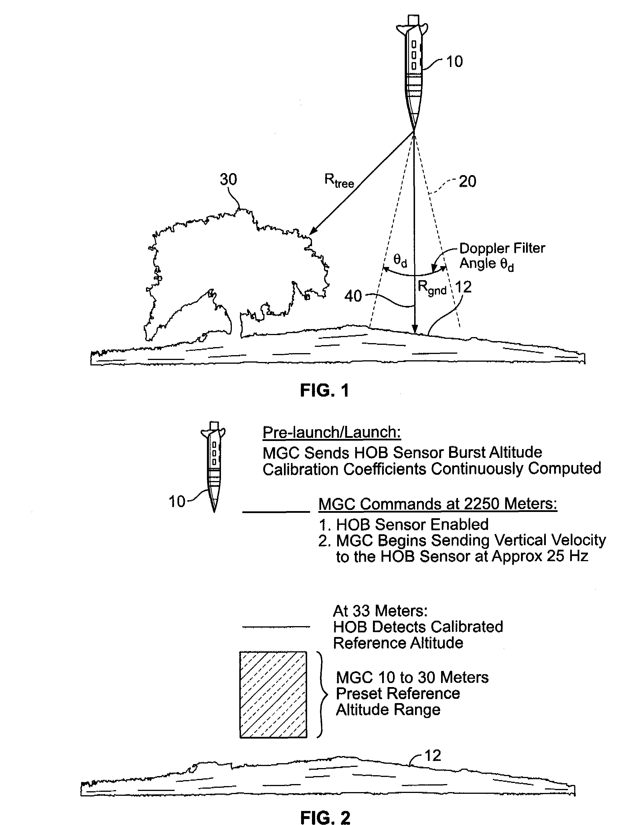
[0025]FIG. 1 is an illustration of radar beam sharpening related to a weapon 10 approaching a target 12. More specifically, Doppler components of the radar return signal are band pass filtered to restrict the field of view of the radar. By restricting the filter bandwidth the radar field of view can be limited to a maximum Doppler angle. Restricting the width to that of the Doppler filter angle, as illustrated in FIG. 1, ensures that radar returns reflecting from tree 30 are not processed by the receiver of the radar and the forward view of weapon 10 is restricted to be along a velocity vector 40. With respect to the radar receiver, the band pass filter is tuned to a center frequency consistent with an expected velocity of a the weapon 10, which is typically derived inertially. Objects providing radar returns that are not along the velocity vector 40 (e.g., off to the side of the missile trajectory) have lower Doppler frequencies and are outside the Doppler filter angle and hence th...


PUM


Abstract

A radar sensor is described that includes a radar transmitter, a radar receiver configured to receive reflected returns of signals output by the radar transmitter, and a signal processing unit configured to process signals received by the radar receiver. The signal processing unit includes a comparator, a first filter comprising an output coupled to a reference input of the comparator, and a second filter comprising an output coupled to a signal input of the comparator. The first and second filters are configured to receive a common input related to the reflected returns. The first filter is configured to have a time constant such that a rise time of the first filter output is faster than a rise time of the second filter output.

Description

BACKGROUND OF THE INVENTION[0001]This invention relates generally to pulse radar operation, and more specifically, to methods and systems that provide an adaptive threshold for beam sharpening within a pulse Doppler radar.[0002]There have been recent developments, for example, relating to the control of a detonation altitude in pulse radar equipped munitions. At least one of these developments utilizes beam sharpening with respect to transmissions from the munitions. This development makes use of the Doppler component on the radar signal to sharpen the beam which limits the forward view of the missile such that it looks along a velocity vector of the falling missile. Conceptually, sharpening the beam involves tuning a band-pass filter to the expected velocity of a missile, which is typically derived inertially within the missile. Objects to the side of the missile have lower Doppler frequencies and therefore a bandwidth of the filter limits the extent that the radar sees to the side...

Claims


Application Information

Patent Timeline
IPC IPC(8): G01S13/08
CPCF42C13/042G01S13/882G01S13/60
Inventor THOMAS, STEVEN H.REILLY, TIMOTHY J.WINSTEAD, BENJAMIN J.
Owner HONEYWELL INT INC
Why Eureka
Try Eureka