Corrugated pattern forming sheet and method for manufacturing the same, and method for manufacturing antireflector, retardation plate, original process sheet plate, and optical element

Inactive Publication Date: 2007-11-29
OJI PAPER CO LTD
View PDF4 Cites 11 Cited by
  • Summary
  • Abstract
  • Description
  • Claims
  • Application Information

AI Technical Summary

Benefits of technology

[0015] The invention has been made in view of the above situations. Therefore, an object of the invention is to provide a corrugated pattern forming sheet exhibiting excellent performance when being used as optical elements, such as an antireflector and a retardation plate. Another object of the invention is to provide a method for manufacturing a corrugated pattern forming sheet capable of simply and easily manufacturing such a corrugated pattern forming sheet with large area. Still another object of the invention is to provide an antireflector with a low reflectance, and a retardation plate which causes the same retardation over a broad wavelength range. A still further object of the invention is to provide an original process sheet plate capable of simply and easily manufacturing a suitable sheet forming a corrugated pattern as an optical element on a large scale. A still further object of the invention is to provide a method for manufacturing an optical element capable of simply and easily manufacturing an optical element having a corrugated pattern of a suitable average pitch and average depth for an optical element on a large scale.
[0027] Since a fine corrugated pattern can be easily formed in a surface with a large area by the method for manufacturing a corrugated pattern forming sheet of the invention, the corrugated pattern forming sheet which can be suitably utilized for optical elements, etc. can be easily and simply manufactured with large area on a large scale.
[0028] The antireflector of the invention has a low reflectance, and has excellent performance.
[0029] The retardation plate of the invention can cause the same retardation over a broad wavelength range, and has excellent performance.
[0030] By using the original process sheet plate of the present invention, a sheet forming a corrugated pattern of a suitable average pitch and average depth for an optical element can be simply and easily manufactured on a large scale.
[0031] According to a method for manufacturing an optical element of the present invention, an optical element having a corrugated pattern of a suitable average pitch and average depth for an optical element can be simply and easily manufactured on a large scale.

Problems solved by technology

However, none of the corrugated pattern forming sheets described in JP-A-Sho63-301988, JP-A-2003-187503, and “Nature” written by Ned Bowden show excellent performance as optical elements.
Specifically, when the corrugated pattern forming sheets are used as antireflectors, the reflectance cannot be made low enough, and when the corrugated pattern forming sheets are used as retardation plates, the retardation cannot be made large enough, and the same retardation cannot be caused over a broad wavelength range.
However, a corrugated pattern forming sheet with a pitch below the wavelength of the light that can be utilized as an optical element cannot be manufactured by this method.
However, when the ultraviolet laser interferometer method or electron beam lithography is applied, there is a problem in that this method is not suitable for mass production because processing in a broad region which exceeds 10 cm is difficult.
However, there is a problem in that this method is also not suitable for mass production because processing in a broad region which exceeds 30 cm is difficult.

Method used


Image

  • Corrugated pattern forming sheet and method for manufacturing the same, and method for manufacturing antireflector, retardation plate, original process sheet plate, and optical element
  • Corrugated pattern forming sheet and method for manufacturing the same, and method for manufacturing antireflector, retardation plate, original process sheet plate, and optical element
  • Corrugated pattern forming sheet and method for manufacturing the same, and method for manufacturing antireflector, retardation plate, original process sheet plate, and optical element

Examples


manufacture example 1

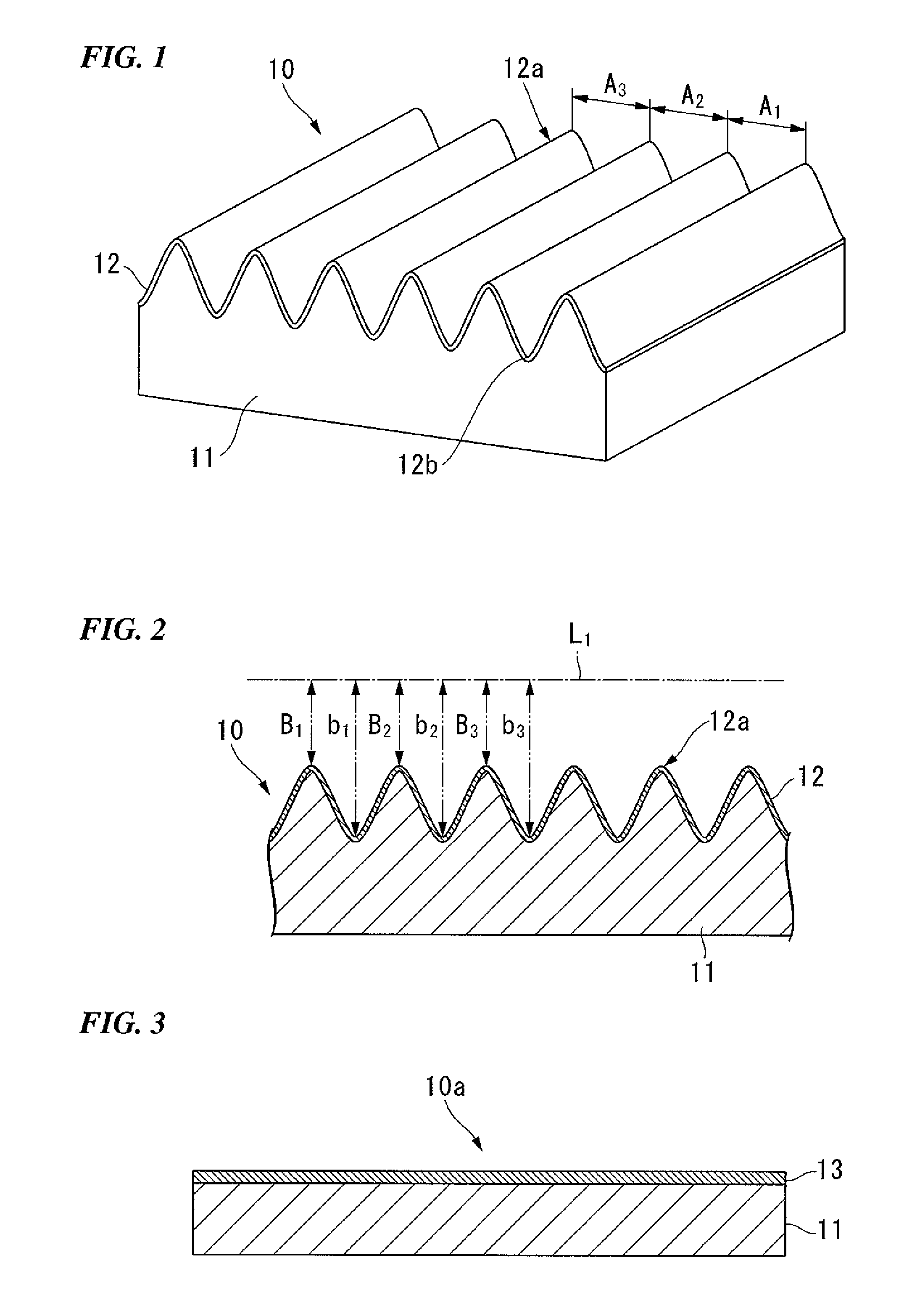
[0159] A laminated sheet was obtained by vacuum-depositing titanium having a Young's modulus of 115 GPa on one surface of a polyethylene terephthalate shrink film (Hishipet LX-10S made by Mitsubishi Plastics, Inc.) that thermally shrinks uniaxially, has a thickness of 50 μm, and has a Young's modulus of 3 GPa so as to have a thickness of 3 nm, thereby forming a smooth surface hard layer.

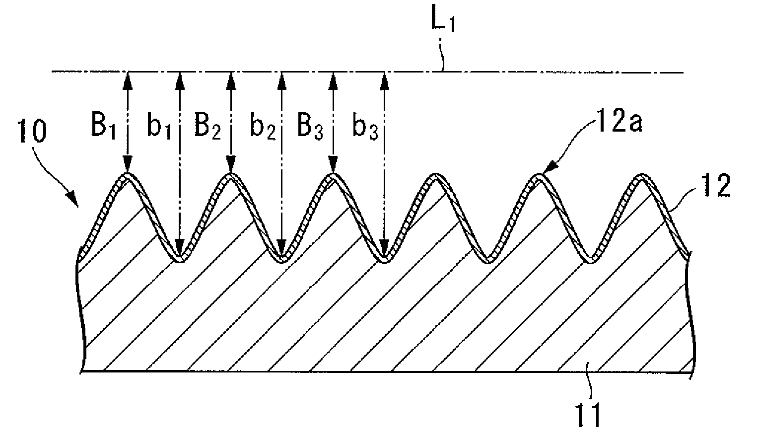
[0160] Next, a corrugated pattern forming sheet whose hard layer has a wavelike corrugated pattern which has a period in a direction orthogonal to a shrinking direction was obtained by heating the laminated sheet for 1 minute at 100° C., and making the sheet thermally shrink to 40% of a length before heating (that is, making the sheet deformed at a deformation ratio of 60%).

manufacture example 2

[0161] A corrugated pattern forming sheet was obtained similarly to Manufacture Example 1 except for vacuum-depositing titanium so as to have a thickness of 7 nm.

manufacture example 3

[0162] A corrugated pattern forming sheet was obtained similarly to Manufacture Example 1 except for heating the laminated sheet for 1 minute at 75° C., and making the sheet thermally shrink to 70% of a length before heating (that is, making the sheet deformed at a deformation ratio of 30%).


PUM

PropertyMeasurementUnit
Fractionaaaaaaaaaa
Fractionaaaaaaaaaa
Depthaaaaaaaaaa

Abstract

A corrugated pattern forming sheet exhibiting excellent performance when being used as optical elements, such as an antireflector and a retardation plate is provided. A corrugated pattern forming sheet of the invention includes a resin layer, and a hard layer provided at least in a portion of an outer surface of the resin layer. The hard layer is made of a metal or a metallic compound. The hard layer has a wavelike corrugated pattern. The average pitch of the corrugated pattern is 1 μm or less, and the average depth of the bottom of the corrugated pattern is 10% or more given an average pitch of 100%.

Description

TECHNICAL FIELD [0001] The present invention relates to a corrugated pattern forming sheet provided in optical elements, such as an antireflector and a retardation plate, and a method for manufacturing the same. The present invention also relates to an antireflector and a retardation plate in which the corrugated pattern forming sheet is used. The present invention also relates to an original process sheet plate, which is used as a die for manufacturing a sheet having a corrugated pattern. Moreover, the present invention relates to a method for manufacturing an optical element. [0002] Priority is claimed to Japanese application No. 2006-131281, filed May 10, 2006, Japanese application No. 2007-040693, filed Feb. 21, 2007, and Japanese application No. 2007-104714, filed Apr. 12, 2007, which is incorporated herein by reference. BACKGROUND OF THE INVENTION [0003] It is known (refer to “Optics” (Volume 27, No. 1, 1998, Pages 12-17) written by Hisao Kikuta and Koichi Iwata and issued by ...

Claims


Application Information

Patent Timeline
IPC IPC(8): G02B5/18B32B3/28B32B7/02B32B9/00B32B15/08G02B1/11G02B1/118G02B5/30
CPCB29D11/00G02B1/11Y10T428/24694Y10S359/90B29D11/00788G02B5/3083
Inventor OKAYASU, TOSHIKI
Owner OJI PAPER CO LTD
Why Eureka
Try Eureka