Laser illuminator

Inactive Publication Date: 2007-11-29
NAT INST OF ADVANCED IND SCI & TECH
View PDF8 Cites 30 Cited by
  • Summary
  • Abstract
  • Description
  • Claims
  • Application Information

AI Technical Summary

Benefits of technology

[0095] In the laser illuminator, the inclination angle of the mirror with respect to the laser beam may be acute or obtuse angle, although 45° is preferable from a standpoint of designing the laser illuminator easily (cf FIGS. 1-2(a), 1-2(b)).
[0096] The laser illuminator is preferably provided w

Problems solved by technology

However, when a relatively small object to be observed using a microscope is illuminated, a laser beam radiating with a multimode cannot be used as a proper light source as it is, because un-uniformity of the un-uniform intensity spatial distribution becomes visible.
Therefore, even if the center area of the laser beam having a relatively uniform intensity spatial distribution is selectively used, the intensity spatial distribution of the selected area cannot be completely uniform and a large portion of the power of the laser beam is consumed wastefully.
However, variations in intensity due to interference of the laser beam cannot be overcome absolutely.
However, since a laser beam has a high coherence, interference noises called speckle noises occur.
A light intensity becomes extremely high at an area where the phase is accidentally in order, while the light intensity becomes zero at an area where the phase is out of order by 180°, which results in generating a spot noise of a granular pattern.
However, in this method, uniformity is not satisfactory and a large amount of light is scattered.
However, the bundle structure using plural optical fibers has particularly a large incident loss and the total light transmittance is at most 50%.
When the structure is used at resolutio

Method used


Image

  • Laser illuminator
  • Laser illuminator
  • Laser illuminator

Examples


Example

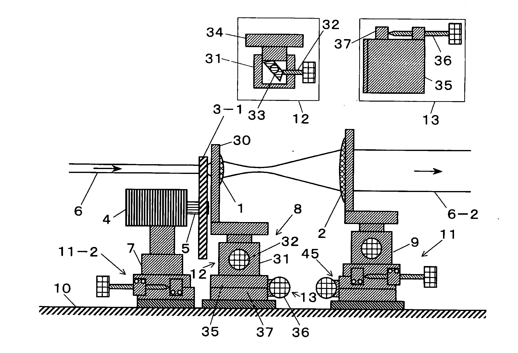
[0238]FIG. 4 shows a first embodiment of a laser illuminator according to the present invention. The laser illuminator in the first embodiment is provided with an optical diffusion plate 3-1 as an optical diffusion means and a combination of a condenser lens 1 and a collimator lens 2 as an optical suppression means for suppressing divergence of light, each of which is disposed on an optical path of a laser beam 6 as explained in FIGS. 2, 2-1, and 2-2.

[0239] As a laser beam 6, a continuous-wave green laser using a second harmonic of a YVO4 laser, 532 nm in wavelength, 1 mm in luminous flux diameter, and 3 mW in intensity, excited by a semiconductor laser is used.

[0240] The optical diffusion plate 3-1 (holographic optical diffusion plate manufactured by Edmond Co., Ltd. Trade name: Holographic diffusion plate) is connected to a motor shaft 5 of a motor 4, which is supported on a stage 7 disposed on a reference surface 10 so as to rotate or vibrate the optical diffusion plate 3-1 in ...

Example

[0247]FIG. 5 shows a laser illuminator according to a second embodiment of the present invention. In the second embodiment, a front and back adjusting mechanism 11 can adjust degree of parallelization of a parallel light beam generated from laser beam 6. Moreover, both a condenser lens 1 and a collimator lens 2 are mounted on a sole common support stage 38. A micro motion stage 14 can be adjusted by means of a vertical adjusting mechanism 12 and a tilt adjusting mechanism 39 (tilting adjustment mechanism).

[0248] The tilt adjusting mechanism 39 can adjust height and tilt adjustment by screws 42 set in a windage stage 41 supporting a cylindrical stage 31 with respect to a base stage 40 mounted on a reference surface 10. This structure allows fine alignment of the optical path of the parallel light beam generated from laser beam 6.

Example

[0249]FIG. 6 shows a laser illuminator according to a third embodiment of the present invention. The third embodiment is substantially the same as the second embodiment. However, a common support stage 38 can be tilted by means of screws 42 with respect to a windage stage 41 (for example, it is indicated as a cross section of a cylinder here) which is vertically adjustable by means of a vertical adjusting mechanism 12.


PUM


Abstract

A laser illuminator comprising at least one optical diffusion means capable of modifying an optical diffusion condition (3) and at least one optical suppression means for suppressing divergence of light (100), wherein the optical diffusion means and the optical suppression means are disposed along an optical path of a laser beam (6) radiating from a laser source and the laser beam is converted into a diffused and non-divergent light beam (6-2) for illuminating or exciting an object by passing through the optical diffusion means and the optical suppression means.

Description

TECHNICAL FIELD [0001] The present invention relates to a laser illuminator for illuminating an object with a laser beam uniformly (equally) and brightly. BACKGROUND OF THE RELATED ART [0002] A laser beam has an intensity spatial distribution with respect to a plane perpendicular to the traveling direction thereof. When a laser beam is used as a light source, it is required to use a center area of the laser beam having a more uniform intensity spatial distribution or to make the un-uniform intensity spatial distribution uniform in any suitable manners. [0003] A laser beam radiating with a multimode which has a very complicated intensity spatial distribution, can illuminate a relatively large object uniformly. However, when a relatively small object to be observed using a microscope is illuminated, a laser beam radiating with a multimode cannot be used as a proper light source as it is, because un-uniformity of the un-uniform intensity spatial distribution becomes visible. [0004] In ...

Claims


Application Information

Patent Timeline
IPC IPC(8): F21K2/00
CPCG02B5/0221G02B5/0252G02B27/48G02B5/0289G02B26/0808G02B5/0278
Inventor NAGAMUNE, YASUSHI
Owner NAT INST OF ADVANCED IND SCI & TECH
Why Eureka
Try Eureka