Compensation of i-q imbalance in digital transceivers

a digital transceiver and imbalance technology, applied in the field of digital transceivers, can solve problems such as imbalances in transmitter and receiver, inability to generate a perfect complex sinusoid using analog circuits, and problems such as distortion of transmitter and receiver

Inactive Publication Date: 2007-11-29
MICROCHIP TECH INC
View PDF53 Cites 91 Cited by
  • Summary
  • Abstract
  • Description
  • Claims
  • Application Information

AI Technical Summary

Benefits of technology

[0025] Embodiments of the present invention may be employed with various transceiver architectures, including, but not limited to, direct conversion, high IF and low IF super-heterodyne, and wideband IF (also known as indirect zero-IF) architectures. Moreover, embodiments of the invention may be easily employed in various communication modes, such as, but not limited to, time-division duplex (TDD) systems and frequency-division duplexed (FDD) systems.

Problems solved by technology

Folding of image in-band is a problem especially if the value of ωi−ω0 is small.
In practice, it is not possible to generate a perfect complex sinusoid using analog circuits due to process variation and asymmetry in layouts.
I-Q imbalances introduce distortions in the transmitter and receiver.
Imbalances are the result of asymmetry in circuit layouts and non-uniformity in IC fabrication processes (such as threshold mismatch and device mismatches).
Typical RF transceivers operating at a few GHz may achieve 2 degrees and 2% of phase and amplitude mismatches even with careful layouts.
While the mismatches seem small, they introduce additional distortions in RF systems so that bit-error rate is increased.
Also, the mismatches worsen for higher carrier frequencies, for example millimeter wave.
I-Q imbalance is especially detrimental to high-performance RF systems that use high-order modulations.

Method used


Image

  • Compensation of i-q imbalance in digital transceivers
  • Compensation of i-q imbalance in digital transceivers
  • Compensation of i-q imbalance in digital transceivers

Examples


Embodiment Construction

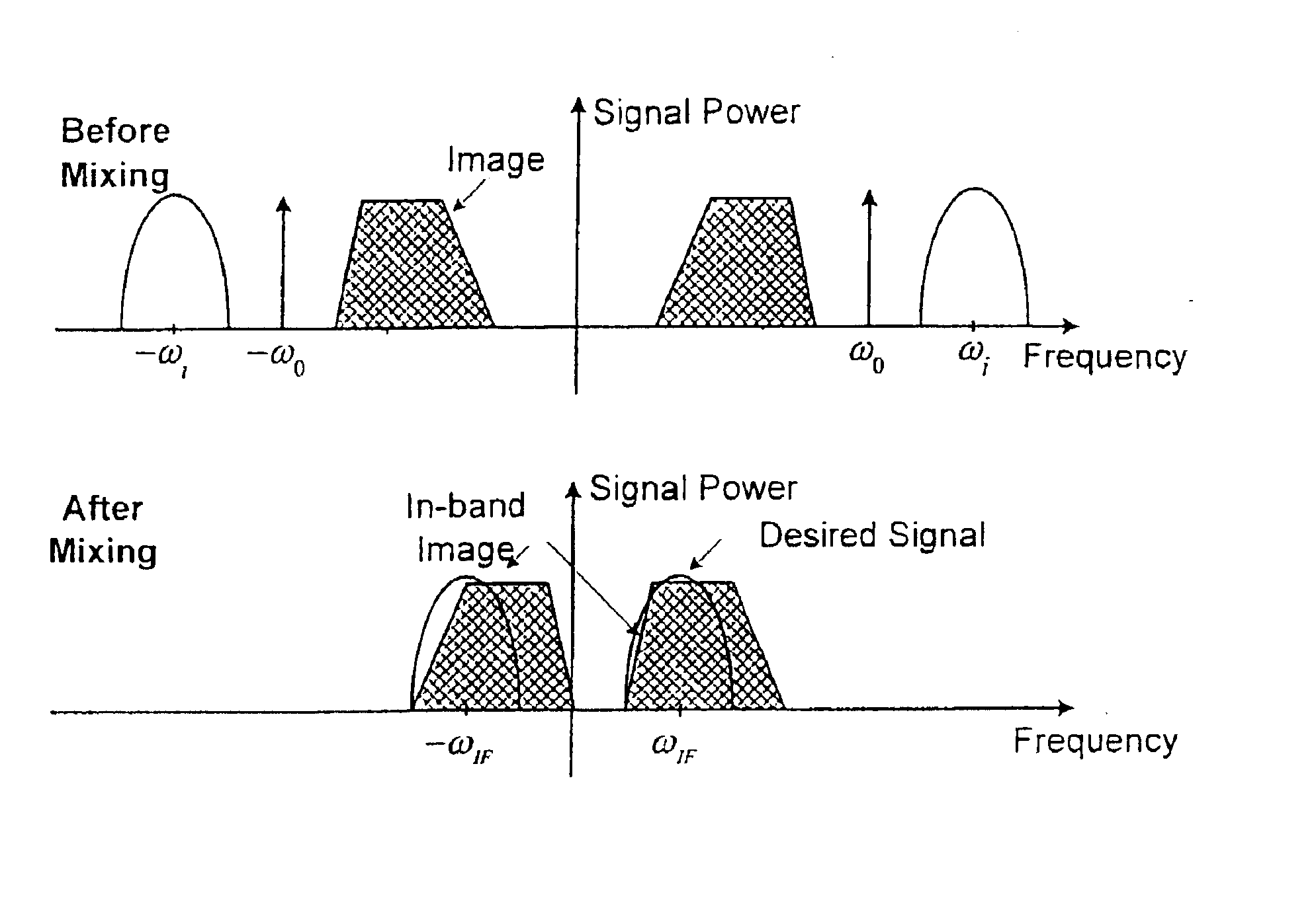
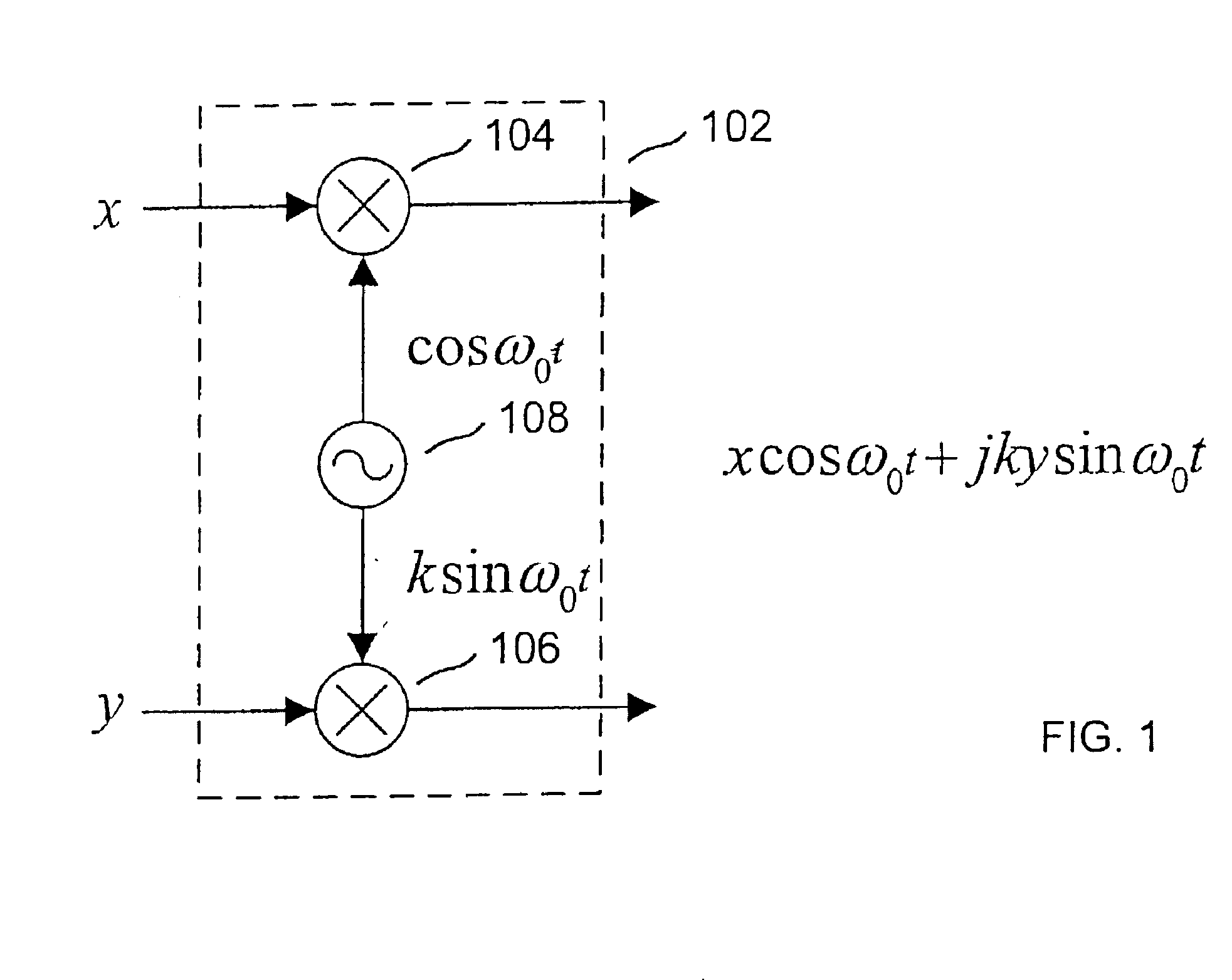
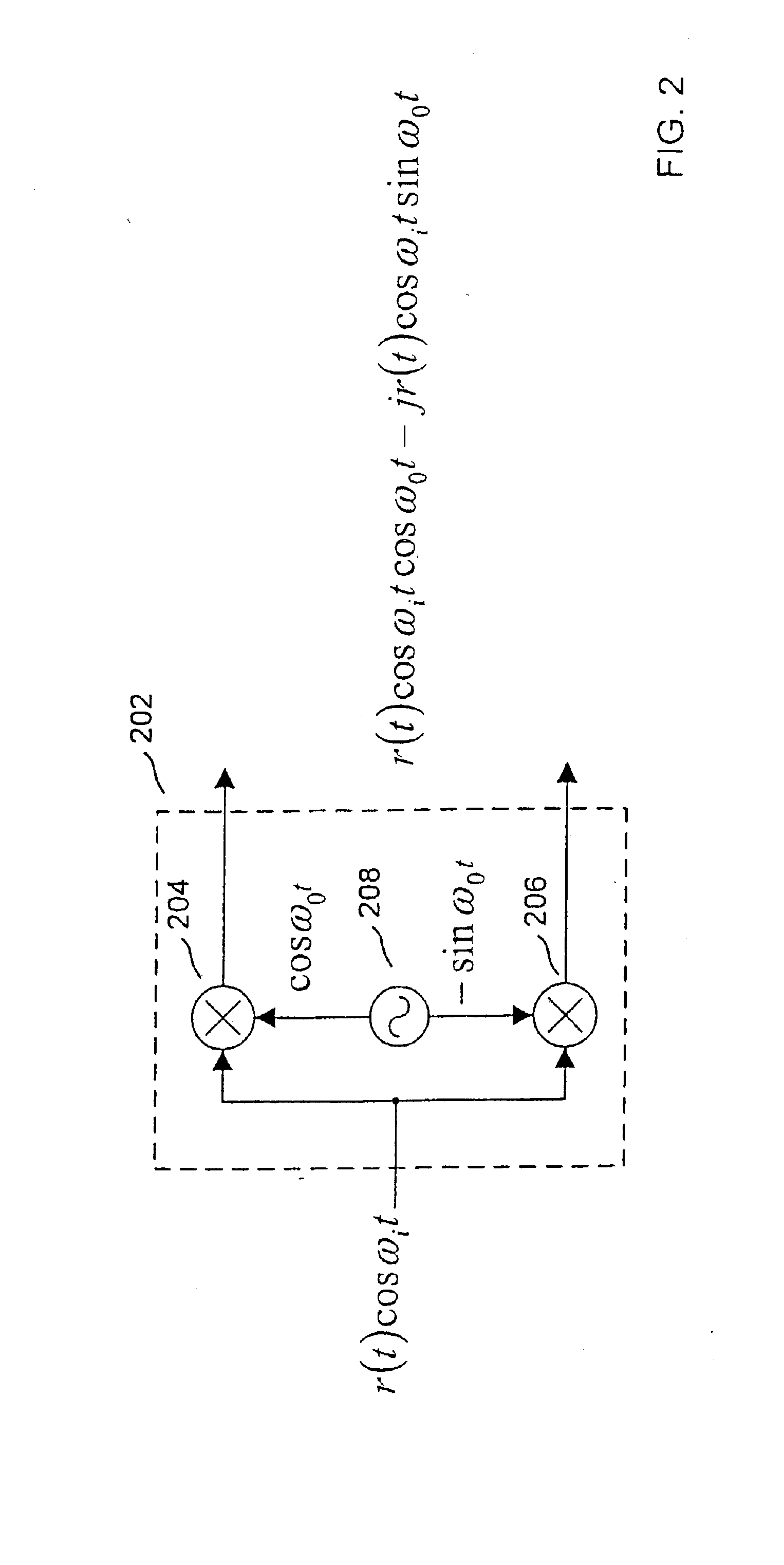
[0079] Embodiments of the present invention reduce I-Q imbalances through compensation using systems and methods that may be implemented with low-complexity and low-cost using existing IC technologies. Moreover, because the present invention lends well to a digital implementation, it may be easily integrated with the existing digital processing that occurs in a RF radio system in one of several possible ways. Non-limiting examples of possible implementations of embodiments of the present invention are shown in FIGS. 6A, 6B and 6C. A two chip solution is shown in FIG. 6A where the compensation is part of a mixed-signal chip that interfaces to the RF with analog-to-digital converters (ADC) and digital-to-analog converters (DAC). The digital function performs modem and medium access (MAC) processing. Another approach is shown in FIG. 6B where the compensation is part of the RF front-end with a general programmable digital interface bus, that may be serial, parallel, or a mixture of bot...


PUM


Abstract

A transceiver includes a switching unit configurable for isolating an input of a receiver from an output of a transmitter during a local calibration mode. A known signal present at the output at a first power level during the calibration mode will also be present at the input at a second power level lower than the first power level and will be converted by the quadrature demodulator. A compensation factor is estimated for compensating the receiver section for imbalances in the in-phase and quadrature phase signals resulting from conversion of the known signal. Remote calibration is implemented using a method for remotely compensating for I-Q imbalance wherein a data packet having a known signal is transmitted to a receiver for conversion by a quadrature demodulator and compensation factors are estimated for compensating for imbalances in the in-phase and quadrature phase signals resulting from conversion of the known signal.

Description

CROSS-REFERENCE TO RELATED APPLICATION(S) [0001] This is a continuation of application Ser. No. 10 / 235,389, filed Sep. 5, 2002, published as U.S. patent application publication No. US2004 / 0203472A1, which is incorporated herein by reference in its entirety.BACKGROUND OF THE INVENTION [0002] 1. Field of the Invention [0003] Embodiments of the present invention relate to digital transceivers for use in communication systems, and in preferred embodiments, to systems and methods for providing compensation for I-Q imbalance in digital transceivers. [0004] 2. Description of Related Art [0005] In communication systems, quadrature up and down-conversion are needed to perform frequency translations. In general, the transmitter uses a quadrature up converter to convert a signal to a higher frequency while the receiver uses a quadrature down converter to convert a signal to a lower frequency. An example of a quadrature converter 102 is shown in FIG. 1. Quadrature converter 102 includes two mix...

Claims


Application Information

Patent Timeline
Patent Type & Authority Applications(United States)
IPC IPC(8): H04B1/40H04B1/30H04B17/00H04L27/00
CPCH04B1/30H04L27/0014H04B17/20H04L2027/0024H04L2027/0016
Inventor CHIEN, CHARLES
Owner MICROCHIP TECH INC
Why Eureka
Try Eureka